800G-2L3KL4L2
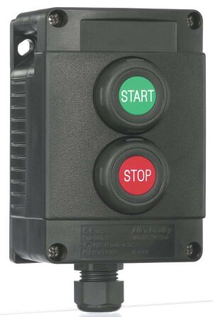
Assembled Station 800G PB
Rockwell Automation announces that as of November 08, 2021, the Assembled Station 800G PB will be discontinued and no longer available for sale. Customers are encouraged to remove references to the affected product(s)
Discontinued Date:
November 08, 2021
Replacement Category:
Engineering Replacement
| Number of push buttons |
1
|
|---|---|
| Number of operator positions |
2
|
| Pushbutton & pilot light color |
Red
|
| Contact block/lamp module position 1 |
1 NO with lA module
|
| Contact block/lamp module position 2 |
1 NC with lA module
|
| Material |
Enclosure/housing material: Thermoplastic, Seal material: EPDM
|
| Operator position 2 |
Illuminated flush push button
|
| Operator position 1 |
Illuminated flush push button
|
| Conduit/cable entry |
Bottom, 3/4 in NPT hub
|
| Mounting |
Power module/contact block combination with screw termination, Base mount: Secures to rail integral to enclosure base, Panel mount: Secures to operator with integral latch
|
| Number of indicator lights |
1
|
| Material housing |
Plastic
|
| PE conductor terminals |
4 x 2.5 mm² stranded maximum
|
| Cable glands, custom |
Metal M20 for cable, outer sheath: Ø 15.5...21.1 mm (Ø 0.61...0.83 in), Metal M25 for cable, outer sheath: Ø 20.3...27.4 mm (Ø 0.80...1.08 in), 19.05 mm (3/4 in) NPT conduit hub
|
| Operating temperature |
-55 °C
|
|---|---|
| Storage temperature |
-55 °C
|
| Storage/transport temperature |
Power module/contact block with cable termination: -30...70 °C
|
| Cable glands, standard |
12.7 mm (1/2 in) NPT conduit hub
|
| Enclosure size |
2 unit enclosure
|
|---|---|
| Power consumption |
Power module/contact block combination with screw/cable termination: ≤1 W
|
| Thermal continuous current |
Power module/contact block combination with screw/cable termination: 1 A
|
| Rated voltage per UL contact rating, max |
Power module/contact block combination with screw/cable termination: 600V AC/DC
|
| Rated insulation voltage |
Power module/contact block combination with screw/cable termination: 300V
|
| Rated voltage |
Power module/contact block with screw/cable termination: 24...48V DC @ 24...250V AC
|
| Rated insulation voltage, max |
690V AC
|
| Contact rating |
A600/P600 per UL 508 with screw/cable termination
|
| Impact resistance |
Illuminated flush push button operator: 7 Nm
|
|---|---|
| Mechanical life operations |
Power module/contact block with screw/cable termination: 100000 hr
|
| Wire/cable size |
Screw termination: 2.5 mm² (12 AWG) stranded maximum
|
| Shock resistance |
Power module/contact block combination with screw/cable termination: DIN IEC 68 part 2-27, 30 G, 18 ms
|
| Degree of protection |
Power module/contact block combination with screw termination: IP20, with operators and enclosure IP66
|
| Operating force |
Illuminated flush push button operator (excludes contact block): 6.7 N
|
| B10D value for base mount contact block with screw termination |
1200000 cycles (The B10D value [cycles] states the number of switching cycles up to which 10% of the elements failed dangerously. The determination was done via a statistical evaluation of field data)
|
| B10D value for latch mount contact block with screw/cable termination |
1200000 cycles (The B10D value [cycles] states the number of switching cycles up to which 10% of the elements failed dangerously. The determination was done via a statistical evaluation of field data)
|
| MTTFD of illuminated flush push button |
3.92E+02 yr @ base mount/latch mount power module with contact block (screw termination) or latch mount power module with contact block (cable termination) (The operating hours of all delivered products or comparable product clusters are determined an
|
| LambdaD of illuminated flush push button |
2.91E-07 Dangerous failures/Years @ base mount/latch mount power module with contact block (screw termination) or latch mount power module with contact block (cable termination) (The operating hours of all delivered products or comparable product cluster
|
| Degree of protection (NEMA) |
4X
|
| Degree of protection (IP) |
IP66
|
| Stranded wire/cable size, max |
2.5 mm²
|
| List of degrees of protection (IP) |
IP54, IP66
|
| Ingress protection rating |
Front of panel operators IP66: -20...70 °C (-4...158 °F), IP54: -55...-20 °C (-67...-4 °F), Type 4X: -20...70 °C (-4...158 °F)
|
| Type | Resource | Publication |
|---|---|---|
| Technical Data | 800-td011_-en-p | 800-TD011 |
Looking for more documentation?
Find curated technical documentation for this product in the Technical Documentation Center, or search our full Literature Library.
Search the Literature Library
Looking for more Technotes?
Find questions and answers from Rockwell Automation technical experts for this product in our Knowledgebase.
Search Knowledgebase
Technical Specifications
| Number of push buttons |
1
|
|---|---|
| Number of operator positions |
2
|
| Pushbutton & pilot light color |
Red
|
| Contact block/lamp module position 1 |
1 NO with lA module
|
| Contact block/lamp module position 2 |
1 NC with lA module
|
| Material |
Enclosure/housing material: Thermoplastic, Seal material: EPDM
|
| Operator position 2 |
Illuminated flush push button
|
| Operator position 1 |
Illuminated flush push button
|
| Conduit/cable entry |
Bottom, 3/4 in NPT hub
|
| Mounting |
Power module/contact block combination with screw termination, Base mount: Secures to rail integral to enclosure base, Panel mount: Secures to operator with integral latch
|
| Number of indicator lights |
1
|
| Material housing |
Plastic
|
| PE conductor terminals |
4 x 2.5 mm² stranded maximum
|
| Cable glands, custom |
Metal M20 for cable, outer sheath: Ø 15.5...21.1 mm (Ø 0.61...0.83 in), Metal M25 for cable, outer sheath: Ø 20.3...27.4 mm (Ø 0.80...1.08 in), 19.05 mm (3/4 in) NPT conduit hub
|
| Operating temperature |
-55 °C
|
|---|---|
| Storage temperature |
-55 °C
|
| Storage/transport temperature |
Power module/contact block with cable termination: -30...70 °C
|
| Cable glands, standard |
12.7 mm (1/2 in) NPT conduit hub
|
| Enclosure size |
2 unit enclosure
|
|---|---|
| Power consumption |
Power module/contact block combination with screw/cable termination: ≤1 W
|
| Thermal continuous current |
Power module/contact block combination with screw/cable termination: 1 A
|
| Rated voltage per UL contact rating, max |
Power module/contact block combination with screw/cable termination: 600V AC/DC
|
| Rated insulation voltage |
Power module/contact block combination with screw/cable termination: 300V
|
| Rated voltage |
Power module/contact block with screw/cable termination: 24...48V DC @ 24...250V AC
|
| Rated insulation voltage, max |
690V AC
|
| Contact rating |
A600/P600 per UL 508 with screw/cable termination
|
| Impact resistance |
Illuminated flush push button operator: 7 Nm
|
|---|---|
| Mechanical life operations |
Power module/contact block with screw/cable termination: 100000 hr
|
| Wire/cable size |
Screw termination: 2.5 mm² (12 AWG) stranded maximum
|
| Shock resistance |
Power module/contact block combination with screw/cable termination: DIN IEC 68 part 2-27, 30 G, 18 ms
|
| Degree of protection |
Power module/contact block combination with screw termination: IP20, with operators and enclosure IP66
|
| Operating force |
Illuminated flush push button operator (excludes contact block): 6.7 N
|
| B10D value for base mount contact block with screw termination |
1200000 cycles (The B10D value [cycles] states the number of switching cycles up to which 10% of the elements failed dangerously. The determination was done via a statistical evaluation of field data)
|
| B10D value for latch mount contact block with screw/cable termination |
1200000 cycles (The B10D value [cycles] states the number of switching cycles up to which 10% of the elements failed dangerously. The determination was done via a statistical evaluation of field data)
|
| MTTFD of illuminated flush push button |
3.92E+02 yr @ base mount/latch mount power module with contact block (screw termination) or latch mount power module with contact block (cable termination) (The operating hours of all delivered products or comparable product clusters are determined an
|
| LambdaD of illuminated flush push button |
2.91E-07 Dangerous failures/Years @ base mount/latch mount power module with contact block (screw termination) or latch mount power module with contact block (cable termination) (The operating hours of all delivered products or comparable product cluster
|
| Degree of protection (NEMA) |
4X
|
| Degree of protection (IP) |
IP66
|
| Stranded wire/cable size, max |
2.5 mm²
|
| List of degrees of protection (IP) |
IP54, IP66
|
| Ingress protection rating |
Front of panel operators IP66: -20...70 °C (-4...158 °F), IP54: -55...-20 °C (-67...-4 °F), Type 4X: -20...70 °C (-4...158 °F)
|
Documents
|
800-td011_-en-p
Technical Data
800-TD011 |
| Type | Resource | Publication |
|---|---|---|
| Technical Data | 800-td011_-en-p | 800-TD011 |
Looking for more documentation?
Find curated technical documentation for this product in the Technical Documentation Center, or search our full Literature Library.
Search the Literature Library
Alternative Products
Technotes
Looking for more Technotes?
Find questions and answers from Rockwell Automation technical experts for this product in our Knowledgebase.
Search Knowledgebase
Loading
Copyright ©2026 Rockwell Automation, Inc.