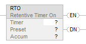
Retentive Timer On (RTO)
This information applies to the
CompactLogix
5370, ControlLogix
5570, Compact GuardLogix
5370, GuardLogix
5570, Compact GuardLogix
5380, CompactLogix
5380, ControlLogix
5580, GuardLogix
5580, and ControlLogix 5590 controllers.The RTO instruction is a retentive timer that accumulates time when the instruction is enabled.
Available Languages
Ladder Diagram
Function Block
This instruction is not available in function block.
Structured Text
This instruction is not available in structured text.
Operands
IMPORTANT:
Unexpected operation may occur if:
- Output tag operands are overwritten.
- Members of a structure operand are overwritten.
- Except when specified, structure operands are shared by multiple instructions.
Ladder Diagram
Operand | Data Type | Format | Description |
Timer | TIMER | tag | Timer structure |
Preset | DINT | immediate | Value of Timer.PRE |
Accum | DINT | immediate | Value of Timer.ACC |
Operand | CompactLogix 5380, ControlLogix 5580, Compact
GuardLogix 5380, GuardLogix 5580, and ControlLogix 5590 controllers Data Type | Format | Description |
Timer | TIMER_T | tag | Timer_T structure |
Accum | TIME | immediate | Value of Timer.ACC |
Preset | TIME | immediate | Value of Timer.PRE |
Preset and Accum (corresponding to .PRE and .ACC in the timer tag) are pseudo-operands. For details, see Pseudo-operand initialization.
TIMER Structure
Mnemonic | Data Type | Description |
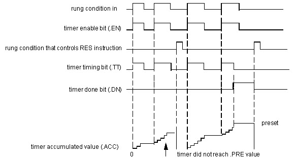
.EN | BOOL | The enable bit contains rung-condition-in when the instruction was last executed. |
.TT | BOOL | The timing bit when set indicates the timing operation is in process. |
.DN | BOOL | The done bit when set indicates the timing operation is complete (or paused). |
.PRE | DINT | The preset value specifies the value (1 millisecond units) which the accumulated value must reach before the instruction indicates it is done. |
.ACC | DINT | The accumulated value specifies the number of milliseconds that have elapsed since the RTO instruction was enabled. |
TIMER_T Structure
Mnemonic | Data Type | Description |
.EN | BOOL | The enable bit contains rung-condition-in when the instruction was last
executed. |
.TT | BOOL | The timing bit when set indicates the timing operation is in process. |
.DN | BOOL | The done bit when set indicates the timing operation is complete (or paused). |
.ACC | TIME | The accumulated value specifies the elapsed time with microsecond fidelity since
the instruction was enabled. |
.PRE | TIME | The preset value specifies with microsecond fidelity the accumulated value that
must be reached before the instruction indicates it is done. |
Description
The RTO instruction accumulates time until:
- The timer is disabled.
- The timer completes.
The time base is always 1 millisecond. For example, for a 2 second timer, enter 2000 for the .PRE value.
The timer will set the .DN bit to true when the timer completes.
When enabled, timing can be paused by setting the .DN bit to true and resumed by clearing the .DN bit to false.
How a Timer Runs
A timer runs by subtracting the time of its last scan from the current time:
ACC = ACC + (current_time - last_time_scanned)
After it updates the ACC, the timer sets last_time_scanned = current_time. This gets the timer ready for the next scan.
Affects Math Status Flags
No
Major/Minor Faults
A major fault will occur if: | Fault type | Fault code |
.PRE < 0 | 4 | 34 |
.ACC < 0 | 4 | 34 |
See Index through arrays for array-indexing faults.
Execution
Ladder Diagram
Condition/State | Action Taken |
Prescan | The .EN bit is cleared to false. The .TT bit is cleared to false. |
Rung-condition-in is false | Set Rung-condition-out to Rung-condition-in. The .EN bit is cleared to false. The .TT bit is cleared to false. |
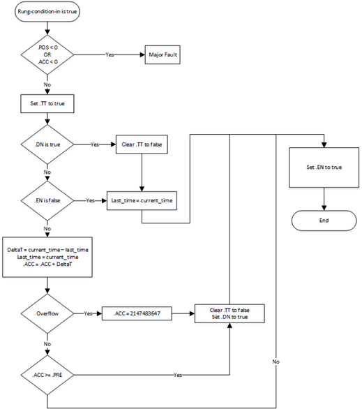
Rung-condition-in is true | Set Rung-condition-out to Rung-condition-in. See RTO Flow Chart (True). |
Postscan | N/A |
RTO Flow Chart (True)
Example
Ladder Diagram
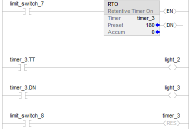
When limit_switch_7 is set, light_2 is on for 180 milliseconds (timer_3 is timing). When timer_3.acc reaches 180, light_2 goes off and light_3 goes on. Light_3 remains on until timer_3 is reset. If limit_switch_7 is cleared while timer_3 is timing, light_2 goes off. When limit_switch_8 is set, the RES instruction resets timer_3 (clears status bits and .ACC value).
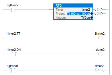
When tglTest2 is set, timing2(with TIMER_T type) is on for 100 milliseconds and 100
microseconds (timer2 is timing). When timer2.acc reaches 100 milliseconds and 100
microseconds, timing2 goes off and done2 goes on. Done2 remains until timer2 is reset. If
tglTest2 is cleared while timer2 is timing, timing2 goes off. When tglreset is set, the RES
instruction resets timer2 (clears status bits and .ACC value).
Provide Feedback