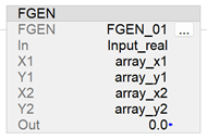
Function Generator (FGEN)
This information applies to the
CompactLogix
5370, ControlLogix
5570, Compact GuardLogix
5370, GuardLogix
5570, Compact GuardLogix
5380, CompactLogix
5380, ControlLogix
5580, GuardLogix
5580, and ControlLogix 5590 controllers.The Function Generator (FGEN) instruction converts an input based on a piece-wise
linear function.
Available Languages
Ladder Diagram
Function Block
Structured Text
FGEN(FGEN_tag,X1,Y1,X2,Y2);
Operands
Ladder Diagram
Operand | Type | Format | Description |
|---|---|---|---|
FGEN tag | FUNCTION_ GENERATOR | structure | FGEN structure |
In | REAL | tag / immediate | The analog signal input to the instruction. Valid = any float |
X1 | REAL | array | X-axis array, table one. Combine with the Y-axis array, table one to define the
points of the first piece-wise linear curve. Valid = any float |
Y1 | REAL | array | Y-axis array, table one. Combine with the X-axis array, table one to define the
points of the first piece-wise linear curve. Valid = any float |
X2 | REAL | array | (optional) X-axis array, table two. Combine with the Y-axis array, table two to define
the points of the second piece-wise linear curve. Valid = any float |
Y2 | REAL | array | (optional) Y-axis array, table two. Combine with the X-axis array, table two to define
the points of the second piece-wise linear curve. Valid = any float |
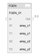
Function Block
Operand | Type | Format | Description |
|---|---|---|---|
FGEN tag | FUNCTION_ GENERATOR | structure | FGEN structure |
X1 | REAL | array | X-axis array, table one. Combine with the Y-axis array, table one to define the
points of the first piece-wise linear curve. Valid = any float |
Y1 | REAL | array | Y-axis array, table one. Combine with the X-axis array, table one to define the
points of the first piece-wise linear curve. Valid = any float |
X2 | REAL | array | (optional) X-axis array, table two. Combine with the Y-axis array, table two to define
the points of the second piece-wise linear curve. Valid = any float |
Y2 | REAL | array | (optional) Y-axis array, table two. Combine with the X-axis array, table two to define
the points of the second piece-wise linear curve. Valid = any float |
Structured Text
Operand | Type | Format | Description |
|---|---|---|---|
FGEN tag | FUNCTION_ GENERATOR | structure | FGEN structure |
X1 | REAL | array | X-axis array, table one. Combine with the Y-axis array, table one to define the
points of the first piece-wise linear curve. Valid = any float |
Y1 | REAL | array | Y-axis array, table one. Combine with the X-axis array, table one to define the
points of the first piece-wise linear curve. Valid = any float |
X2 | REAL | array | (optional) X-axis array, table two. Combine with the Y-axis array, table two to define
the points of the second piece-wise linear curve. Valid = any float |
Y2 | REAL | array | (optional) Y-axis array, table two. Combine with the X-axis array, table two to define
the points of the second piece-wise linear curve. Valid = any float |
See
Structured Text Syntax
for more information on the syntax of expressions
within structured text.FUNCTION_GENERATOR
Structure
Input Parameter | Data Type | Description |
|---|---|---|
EnableIn | BOOL | Enable input. If false, the instruction does not execute and outputs are not
updated. Default is true. |
In | REAL | The analog signal input to the instruction. Valid = any float Default = 0.0 |
XY1Size | DINT | Number of points in the piece-wise linear curve to use from table one. If the
value is less than one and Select is cleared, the instruction sets the appropriate
bit in Status and the output is not changed. Valid = 1 to (smallest of X1 and Y1 array sizes) Default = 1 |
XY2Size | DINT | Number of points in the piece-wise linear curve to use from table two. If the
value is less than one and Select is set, the instruction sets the appropriate bit
in Status and the output is not changed. Valid = 0 to (smallest of X2 and Y2 array sizes) Default = 0 |
Select | BOOL | This input determines which table to use. When cleared, the instruction uses
table one; when set, the instruction uses table two. Default is cleared. |
Output Parameter | Data Type | Description |
|---|---|---|
EnableOut | BOOL | Indicates if instruction is enabled. Cleared to false on overflow |
Out | REAL | Output of the instruction. |
Status | DINT | Status of the function block. |
InstructFault (Status.0) | BOOL | Instruction generated a fault. |
XY1SizeInv (Status.1) | BOOL | Size of table 1 is invalid or not compatible with the array size. |
XY2SizeInv (Status.2) | BOOL | Size of table 2 is invalid or not compatible with the array size. |
XisOutofOrder (Status.3) | BOOL | The X parameters are not sorted. |
Description
The following illustration shows how the
FGEN instruction converts a twelve-segment curve.
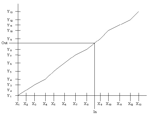
The X-axis parameters must follow the relationship:
X[1] < X[2] < X[3] < ... < X[XY<n>Size],
where XY<n>Size >
1 and is a number of points in the piece-wise linear curve and where n is 1 or 2 for the
table selected. You must create sorted X-axis elements in the X arrays.
The Select
input determines which table to use for the instruction. When the instruction is executing
on one table, you can modify the values in the other table. Change the state of Select to
execute with the other table.
Before calculating Out, the X axis parameters are
scanned. If they are not sorted in ascending order, the appropriate bit in Status is set and
Out remains unchanged. Also, if XY1Size or XY2Size is invalid, the instruction sets the
appropriate bit in Status and leaves Out unchanged.
The instruction uses this
algorithm to calculate Out based on In:
- When In
 X[1], set Out = Y[1]
 - When In > X[XY<n>Size], set Out = Y[XY<n>Size]
- When X[n] < In X[n+1], calculate Out = ((Y[n+1]-Yn)/ (X[n+1]-Xn))*(In-Xn)+Yn
Affects Math Status Flags
No
Major/Minor Fault
None specific to this instruction. See
Common Attributes for operand-related faults.
Execution
Ladder Diagram
Condition | Function Block Action |
|---|---|
Prescan | Rung-condition-out is cleared to false. |
Rung-condition-in is false | Set Rung-condition-out to Rung-condition-in. |
Rung-condition-in is true | Set Rung-condition-out to Rung-condition-in. |
Postscan | Rung-condition-out is cleared to false. |
Function Block Diagram
Condition | Function Block Action |
|---|---|
Prescan | EnableIn and EnableOut bits are set to false. |
EnableIn is false | EnableIn and EnableOut bits are set to false. |
EnableIn is true | EnableIn and EnableOut bits are set to true. Execute FGEN algorithm. |
Instruction first run | N/A |
Instruction first scan | Set the internal Out to 0.0 Execute FGEN algorithm. |
Postscan | EnableIn and EnableOut bits are set to false. |
Structured Text
Condition/State | Action Taken |
|---|---|
Prescan | EnableIn and EnableOut bits are set to false. |
Normal Execution | EnableIn and EnableOut bits are set to true. Execute FGEN algorithm. |
Postscan | EnableIn and EnableOut bits are set to false. |
Examples
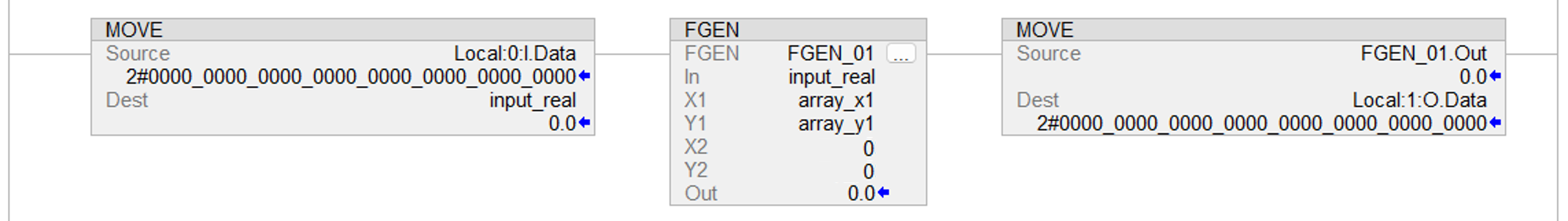
Example 1
In
this example, the FGEN instruction characterizes a flow signal which is then totalized using
a TOT instruction. The FGEN_01X1 and FGEN_01Y1 arrays are REAL arrays of 10 elements each to
support up to a 9 segment curve. You can use arrays of any size to support a curve of any
desired number of segments.
Function Block
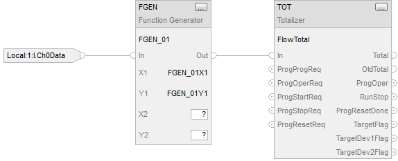
Ladder Diagram
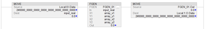
Example 2
This example
passes optional parameters to FGEN instruction.
Function Block

Ladder Diagram
Provide Feedback