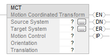
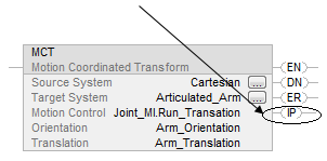
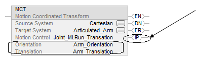
Motion Coordinated Transform (MCT)
This information applies to the
CompactLogix
5370, ControlLogix
5570, Compact GuardLogix
5370, GuardLogix
5570, Compact GuardLogix
5380, CompactLogix
5380, ControlLogix
5580, GuardLogix
5580, and ControlLogix 5590 controllers.Use the Motion Coordinated Transform (MCT) instruction to start a transform that links two
coordinate systems together. This is like bi-directional gearing. One way to use the
transform is to move a non-Cartesian robot to Cartesian positions.
IMPORTANT:
Tags used for the motion control attribute of instructions should only
be used once. Re-use of the motion control tag in other instructions can cause unintended
operation. This may result in damage to equipment or personal injury.
Architecture | Standard | Safety |
|---|---|---|
CompactLogix 5370, ControlLogix 5570, Compact GuardLogix 5370, and GuardLogix 5570 controllers | Yes | No |
Compact GuardLogix 5380, CompactLogix 5380, ControlLogix 5580, GuardLogix 5580,
and ControlLogix 5590 controllers | Yes | No |
Available Languages
Ladder Diagram
Function Block
This instruction is not available in function block.
Structured Text
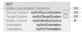
MCT(Source System, Target System, Motion Control, Orientation, Translation);
Operands
Ladder Diagram and Structured Text
Operand | Type | Format | Description | |
|---|---|---|---|---|
Source System | COORDINATE_SYSTEM | Tag | Coordinate system that you use to program the moves. Typically this is the Cartesian coordinate system. Reference to Coordinate system that you use to program the moves. Typically this
is the Cartesian coordinate system. For controllers that support the REF_TO motion
data types, the coordinate system operand type can be replaced by the
REF_TO_COORDINATE_SYSTEM type. | |
Target System | COORDINATE_SYSTEM | Tag | Non-Cartesian coordinate system that controls the actual equipment. Reference to Coordinate system that you use to program the moves. Typically this
is the Cartesian coordinate system. For controllers that support the REF_TO motion
data types, the coordinate system operand type can be replaced by the
REF_TO_COORDINATE_SYSTEM type. | |
Motion Control | MOTION_INSTRUCTION | Tag | Control tag for the instruction. | |
Orientation | REAL[3] (units = coordinate units) | Array | Do you want to rotate the target position around the X1, X2, or X3 axis? | |
If | Then | |||
No | Leave the array vales at zero. | |||
Yes | Enter the degrees of rotation into the array. Put the degrees of rotation around X1 in the first element of the array, and then add the other elements. | |||
Use an array of three REALs even if a coordinate system has only one or two axes. | ||||
Translation | REAL[3] (units = coordinate units) | Array | Do you want to offset the target position along the X1, X2, or X3 axis? | |
If | Then | |||
No | Leave the array values at zero. | |||
Yes | Enter the offset distances into the array. Enter the offset distances in coordinate units. Put the offset distance for X1 in the first element of the array, and then add the other elements. | |||
Use an array of three REALs even if a coordinate system has only one or two axes. | ||||
See Structured Text Syntax for
more information on the syntax of expressions within structured text.
MOTION_INSTRUCTION Data Type
To see if | Check if this bit is on | Data Type | Notes |
|---|---|---|---|
The rung is true | EN | BOOL | Sometimes the EN bit stays on even if the rung goes false. This happens if the rung goes false before the instruction is done or an error has occurred. 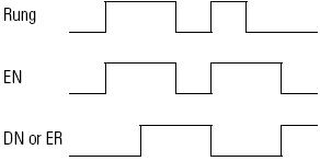 |
The instruction is done. | DN | BOOL | The transform keeps running after the instruction is done. |
An error happened | ER | BOOL | Identify the error number listed in the error code field of the Motion control tag then, refer to Motion Error Codes. |
The transform process is running. | IP | BOOL | Any of these actions cancels the transform and turns off the IP bit: Applicable stop instruction Shutdown instruction Fault action |
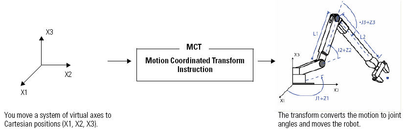
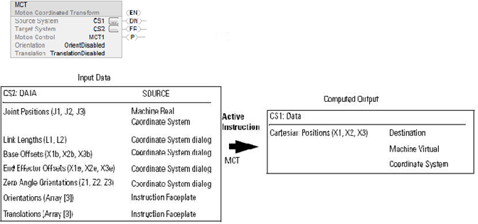
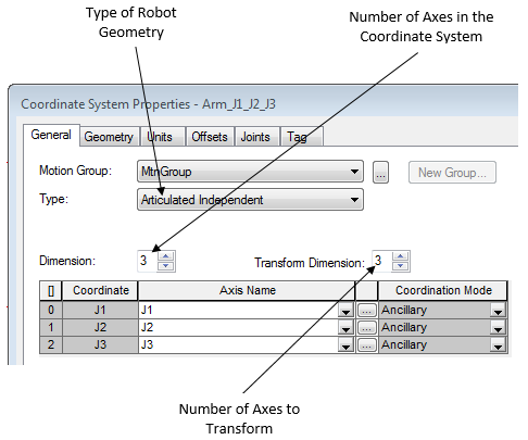
The transform controls up to three joints of the robot: J1, J2, and J3.
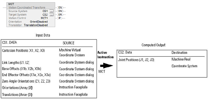
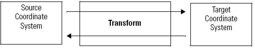
Data Flow of MCT Instruction between Two Coordinate Systems
The following illustrations show the flow of data when an MCT Instruction is active. CS1 is a Cartesian coordinate system containing X1, X2 and X3 axes as the source of the MCT instruction. CS2 is the joint coordinate system containing J1, J2, and J3 axes as the target of the MCT instruction.
All axes units are in Coordinate Units
Follow these guidelines to use an MCTP instruction.
Data Flow When a Move is executed with an MCT Instruction - Forward Transform
Data Flow When a Move is Executed with an MCT Instruction - Inverse Transform
Programming Guidelines
Follow these guidelines to use an MCT instruction.
IMPORTANT:
Do not let the robot get fully stretched or fold back on itself.
Otherwise it can start to move at a very high speed. In those positions, it loses its
configuration as a left or right arm. When that happens, it can start to move at a very high
speed.
Determine the working limits of the robot and keep it within those
limits.
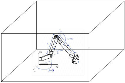
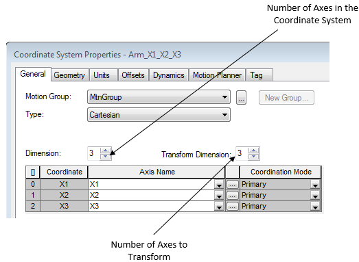
Set up a coordinate system of axes for the Cartesian positions of the robot
These axes are typically virtual.
IMPORTANT:
You may see truncation error in the precision of computations. This
happens when both of these conditions are true:
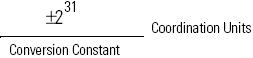
- The conversion constants of the virtual Cartesian axes in a transformation are small, such as 8000 counts/position unit.
- The link lengths of the non-Cartesian coordinate system are small, such as 0.5 inches.
It is best to give large conversion constants to the virtual Cartesian axes in a transform, such as 100,000 or 1,000,000 counts/position unit. The maximum travel limit of the robot is:
Set up another coordinate system for the actual joints of the robot
Move the robot to a left- or right-arm starting position
Do you want the robot to move like a left arm or a right arm?
Before you start the transform, move the robot to a resting position that gives it the arm side that you want (left or right).
Once you start the transform and initiate a Cartesian move in the Source coordinate system, the robot stays as a left arm or a right arm. If it starts as a left arm, it moves as a left arm. If it starts as a right arm, it moves as a right arm. You can always flip it from a left arm to a right arm or vice versa. To do that, move the joints directly.
Toggle the rung from false to true to execute the instruction
This is a transitional instruction. In a ladder diagram, toggle the Rung-condition-in from false to true each time you want to execute the instruction.
When you execute the instruction, the transform starts and the IP bit turns on.
You can let the rung go false once you execute the instruction. The transform stays active.
In structured text, condition the instruction so that it only executes on a transition
Start the transform before you start any motion.
In structured text, instructions execute each time they are scanned. Condition the instruction so that it only executes on a transition. Use one of these methods:
- Qualifier of an SFC action
- Structured text construct
You cannot start a transform if any motion process is controlling an axis of the source or target coordinate systems.
Example: Start the transform before you start gearing or camming.
Expect bi-directional motion between the source and target coordinate systems
Use an MCS instruction to cancel the transform.
A transform is bi-directional.
When you start the transform, the position of the source coordinate system changes to match the corresponding position of the target coordinate system. After that, if you move either system, the other system moves in response.
The controller continues to control the axes even if you stop scanning the MCT instruction or its rung goes false. Use a Motion Coordinated Stop (MCS) instruction to stop the motion in the coordinate system, cancel the transform, or both.
If you change the orientation or translation, execute the MCT instruction again
Then, execute the instruction again. To execute the instruction, toggle the rung-condition-in from false to true.
If you change the geometry of the equipment, execute the instruction again.
Specify and execute more than one orientation angle in the Orientation operand of the MCTP instruction
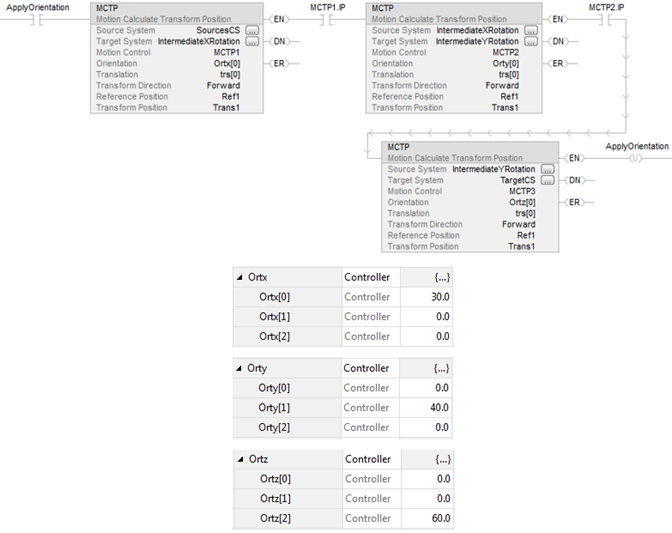
The rotations around X, Y, Z are entered in the following order:
The first element from the first MCTP orientation operand array is used to specify X rotation.
The second element from the second MCTP orientation operand is used to specify Y rotation.
The third element from the third MCTP orientation operand is used to specify Z rotation.
Example
The following table shows before and after rotation orders. Note that the order of rotations in n-Dimensions is not commutative.
Rotation: V20 or greater Matrix Multiply Order: (Z*(YX) Rotate Around X then Y then Z: | |
|---|---|
Rotation Cartesian => Cartesian | Logix Designer V20 or greater |
MCT Orientation [x,y,z] | MCT Starting Position
Resulting Oriented Position |
1 Dimension Rotation | |
Starting Position = [1, 2, 3] | |
MCT Orient=[90, 0, 0] | Rotation: 90 (cw) around X.
= [1, 3, -2] |
MCT Orient=[0, 90, 0] | Rotation: 90 (cw) around Y.
= [-3, 2, 1] |
MCT Orient=[0, 0, 90] | Rotation: 90 (cw) around Z.
= [2, -1, 3] |
2 Dimension Rotation | |
Starting Position = [1, 2, 3] | |
MCT Orient=[90, 90, 0] | Rotation: 90 (cw) around X then 90 (cw) around Y. = [-3, 1, -2] |
MCT Orient=[90, 0, 90] | Rotation: 90 (cw) around X then 90 (cw) around Z. = [2, 3, 1] |
MCT Orient=[0, 90, 90] | Rotation: 90 (cw) around Y then 90 (cw) around Z. = [-3, -1, 2] |
3 Dimension Rotation | |
Starting Position = [1, 2, 3] | |
MCT Orient=[90, 90, 90] | Rotation: 90 (cw) around X then 90 (cw) around Y then 90 (cw) around Z. = [-3, 2, 1] |
MCT Orient=[-90, -90, -90] | Rotation: 90 (ccw) around X then 90 (ccw) around Y then 90 (ccw) around Z. = [3, -2, 1] |
MCT Instruction Guidelines
Affects Math Status Flags
No
Major/Minor Faults
None specific to this instruction. A major fault can occur if an uninitialized reference or
a reference of the incorrect type is passed to the Coordinate System operands. See Common Attributes for operand-related faults.
Execution
Ladder Diagram
Condition/State | Action Taken |
|---|---|
Prescan | The .EN, .DN, .ER, and .IP bits are cleared to false. |
Rung-condition-in is false | The .EN bit is cleared to false if either the .DN or .ER bit is true. |
Rung-condition-in is true | The .EN bit is set to true and the instruction executes. |
Postscan | N/A |
Structured Text
Condition/State | Action Taken |
|---|---|
Prescan | See Prescan in the Ladder Diagram table. |
Normal execution | See Rung-condition-in is false, followed by rung is true in the Ladder Diagram table. |
Postscan | See Postscan in the Ladder Diagram table. |
Error Codes
See Motion Error Codes .ERR for Motion
Instructions.
Extended Error Codes
See Motion Error Codes .ERR for Motion Instructions.
Use Extended Error Codes (EXERR) for more instruction about an error.
ERR | EXERR | Corrective Action | Notes |
|---|---|---|---|
61 | 1 | Assign both coordinate systems to the motion group. | |
2 | Check that you are using the correct source and target systems. | You cannot use the same coordinate system as source and target. | |
3 | Set the transform dimension of the source system to the number of axes in the system, up to three. | ||
4 | Set the transform dimension of the target system to the number of axes in the system to be transformed, up to three. | ||
5 | Use a different source system. | You can only use one coordinate system as the source for one active transform. | |
6 | Use a different target system. | You can only use one coordinate system as the target for one active transform. | |
7 | Look for source or target axes that you are already using in another transform. Use different axes in the coordinate system. | You can only use an axis in one source system and one target system. | |
8 | Use a target system that isn't’t the source for this chain of transforms. | You cannot create a circular chain of transforms that leads back to the original source. | |
9 | Check that you have assigned the correct axes to each coordinate system. | You cannot use the same axes in the source and target systems. | |
10 | Stop all motion processes for all the axes in both systems (for example, jog, move, and gear). | You cannot start the transform if any motion process is controlling a source or target axis. | |
11 | Insufficient resources available to initiate the transform connection. | ||
12 | Set the link lengths. | You cannot use a link length of zero. | |
13 | Look for source or target axes that are in the shutdown state. Use a Motion Axis Shutdown Reset (MASR) instruction or direct command to reset the axes. | ||
14 | Uninhibit all the source or target axes. | ||
15 | Check the configured values for the base offsets and end effector offsets for the Delta or SCARA Delta robot. | (X1b-X1e) cannot be less than 0.0 for both the Delta and SCARA Delta robots. For Delta robots, this error can also occur if the value of L1 + (X1b-X1e) is greater than L2. | |
16 | Check the SCARA independent and SCARA Delta robot configurations to be sure that: The transform dimension for the source coordinate system is configured as 2. The configured third axes for the source coordinate system and the target coordinate system are the same. | ||
17 | Check the source and target coordinate systems to verify that the transform dimension of the source coordinate system equals the transform dimension of the target coordinate system. |
Changes to Status Bits
The instruction changes these status bits when it executes.
To see if | Check the tag for the | And this bit | For |
|---|---|---|---|
A coordinate system is the source of an active transform. | Coordinate System | TransformSourceStatus | On |
A coordinate system is the target of an active transform. | Coordinate System | TransformTargetStatus | On |
An axis is part of an active transform. | Axis | TransformStateStatus | On |
An axis is moving because of a transform. | Axis | ControlledByTransformStatus | On |
Examples
Ladder Diagram
Structured Text
MCT(myMctSourceSystem,myMctTargetSystem,myMctMotionControl,myMctOrientation,myMctTranslation);
Provide Feedback