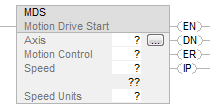
Motion Drive Start (MDS)
This information applies to the CompactLogix 5370, ControlLogix 5570, Compact GuardLogix
5370, GuardLogix 5570, Compact GuardLogix 5380, CompactLogix 5380, ControlLogix 5580,
GuardLogix 5580, and ControlLogix 5590 controllers.
IMPORTANT:
The MDS instruction is validated if the CIP drive device supports the S
ramp attributes, including:
- RampAcceleration
- RampDeceleration
- RampVelocity - Positive
- RampVelocity - Negative
- RampJerk - Control
This is a transitional instruction. Follow these steps when using it:
- In ladder logic, insert an instruction to toggle the rung-condition-in from false to true each time the instruction should execute.
- In a Structured Text routine, insert a condition for the instruction to cause it to execute only on a transition.
Architecture | Standard | Safety |
|---|---|---|
CompactLogix 5370, ControlLogix 5570, Compact GuardLogix 5370, and GuardLogix
5570 controllers | Yes | No |
Compact GuardLogix 5380, CompactLogix 5380, ControlLogix 5580, GuardLogix 5580,
and ControlLogix 5590 controllers | Yes | No |
Available Languages
Ladder Diagram
Function Block
This instruction is not available in function block.
Structured Text
MDS(Axis,MotionControl,Speed,Unitspersec);
Operands
Ladder Diagram and Structured Text
Operand | Type CompactLogix 5370, Compact GuardLogix 5370, Compact GuardLogix 5380, CompactLogix 5380 | Type ControlLogix 5570, GuardLogix 5570, ControlLogix
5580, GuardLogix 5580, and ControlLogix 5590 controllers | Format | Description |
|---|---|---|---|---|
Axis | AXIS_CIP_DRIVE | AXIS_CIP_DRIVE | Tag | Motion Axis of data type AXIS_CIP_DRIVE only. For controllers that support the
REF_TO motion data types, the supported axis operand type can be replaced by an
equivalent REF_TO type. |
Motion Control | MOTION_INSTRUCTION | MOTION_INSTRUCTION | Tag | Structure used to control execution of the motion instruction. |
Speed | SINT INT DINT REAL | SINT INT DINT REAL | Immediate or Tag | Defines the initial speed for the DirectVelocityControlStatus Command
attribute. |
Speed Units | SINT INT DINT | SINT INT DINT | Immediate | Which units do you want to use for the speed? 0 = % of Maximum 1 = Units per Sec |
See Structured Text Syntax for
more information on the syntax of expressions within structured text.
MOTION_INSTRUCTION Structure
Mnemonic | Description |
|---|---|
.EN (Enable) Bit 31 | It is set when the rung makes a false-to-true transition and remains set until
the rung makes a true-to-false transition and drive messaging is complete. |
.DN (Done) Bit 29 | It is set when the drive has been successfully enabled and remains set until the
rung makes a false-to-true transition. |
.ER (Error) Bit 28 | It is set when the instruction encounters an error condition. The error condition
can be a direct result of the initial conditions or may result during the
instruction’s execution. The bit remains set until the rung makes a false-to-true
transition. |
.IP (In process) Bit 26 | It is set when the instruction has been successfully initiated and remains set
until: another MDS instruction supersedes the initial instruction another instruction terminates the initial instruction a drive fault occurs. |
STATE | Reflects the state of the instruction. 0 = Sending a request to the drive module to turn the drive on 1 = Waiting for the drive enable and servo action status bits to be set |
Description
The MDS instruction:
- Is only valid for the AXIS_CIP_DRIVE axis data type.
- Performs a drive enable if the axis is not in the Running state.
- Applies desired DirectVelocityControlStatus Command attribute and/or the DirectTorqueControlStatus Command attributes.
- Presents the DirectVelocityControlStatus Command attributes and/or the DirectTorqueControlStatus Command attributes.
- Is activated on a Rung False-to-True transition.
The MDS instruction is used to activate the direct control of velocity or torque for a
specified axis. The instruction performs an axis enable sequence and then presets the
DirectVelocityControlStatus Command attribute and/or the DirectTorqueControlStatus Command
attribute if the selected drive supports direct control. The most common usage of the MDS
instruction is the flying start application, where the following attributes directly control
the motion dynamics:
- RampAcceleration
- RampDeceleration
- RampVelocity - Positive
- RampVelocity - Negative
- RampJerk - Control
The DirectVelocityControlStatus Command attribute is applied by taking the value in the
speed field in the instruction configuration and copying it into the
DirectVelocityControlStatus Command attribute. The DirectVelocityControlStatus Command
attribute is then scaled and summed onto the commanded output to the drive device. The
DirectVelocityControlStatus Command attribute value can be modified directly via the MOV
instruction.
The DirectTorqueControlStatus Command attribute is applied by taking the value in speed
field in the instruction configuration and copying it into the DirectTorqueControlStatus
Command attribute. The DirectTorqueControlStatus Command attribute is then sent directly to
the drive via the placeholder in the CIP Controller to Drive Connection.
A combination of the DirectVelocityControlStatus Command attribute and the
DirectTorqueControlStatus Command attribute can be applied in applications that require
Speed-limited Adjustable Torque (SLAT) modes. SLAT operation mode provides automatic speed
control under certain conditions.
The SLAT Configuration is an enumerated attribute that determines how the drive controls
torque for this axis instance. To support applications that require SLAT control, the
Min/Max torque control enumerations provide a feature to automatically switch to and from
speed control under certain conditions. In either SLAT mode the drive operates in one of the
states described in the following table.
Enumeration | Mode | Description |
|---|---|---|
0 | SLAT disabled | SLAT function is disabled. This is the normal Velocity Loop operation. |
1 | SLAT Min Speed/Torque | Drive automatically switches from torque control to speed control if Velocity
Error > SLAT set point and switches back to torque control if Speed Error <
0. |
2 | SLAT Max Speed Torque | Drive automatically switches from torque control to speed control if Velocity
Error < -SLAT set point and switches back to torque control if Speed Error >
0. |
When you execute the MDS instruction and the drive is configured for velocity control, the
acceleration and deceleration ramp to the specified speed is controlled by the drives based
on the Acceleration Limit and Deceleration Limit attributes. The Motion Planner takes the
value from the Direct Command Velocity attribute and sums it into the axis output before
sending the command to the drive. The most common use of this instruction is to perform a
Drive Start application into a spinning motor, also known as a Flying Start application.
The axis remains in DirectVelocityControlStatus Command attribute or
DirectTorqueControlStatus Command attribute modes until canceled by one of the following
instructions:
- Motion Axis Stop (MAS)
- Motion Axis Shutdown (MASD)
- Motion Coordinated Shutdown (MCSD)
- Motion Group Shutdown (MGSD)
- Motion Servo Off (MSF)
Depending on how the fault action is configured, an axis fault can also cancel the MDS
instruction.
Execution of the MDS instruction has no effect on motion group or coordinate system
objects. However, the instruction affects axis objects as follows:
When the MDS instruction is initiated without errors, the DirectVelocityControlStatus bit
of the MotionStatus axis attribute is set, indicating the DirectVelocityControlStatus bit is
active on the axis.
The DirectVelocityControlStatus bit remains set until it is made inactive via an MAS or
MASR instruction, or via an axis fault.
Also, when the MDS instruction is initiated without errors, the DirectTorqueControlStatus
bit attribute of the MotionStatus axis attribute is set, indicating the
DirectTorqueControlStatus Command attribute is active on the axis.
The DirectTorqueControlStatus bit remains set until it is made inactive via an MAS or MASR
instruction, or via an axis fault.
Some fault actions impact the execution of the MDS instruction.
Fault Action | Description |
|---|---|
Ignore | Ignore instructs the device to completely ignore the exception condition. For
some exceptions that are fundamental to the operation of the axis, it may not be
possible to Ignore the condition. |
Alarm | Alarm action instructs the device to set the associated bit in the Axis Alarm
word but to otherwise not affect axis behavior. For some exceptions that are
fundamental to the operation of the device, it may not be possible to select this
action or any other action that leaves device operation unaffected. |
Fault Status Only | Fault Status Only instructs the device to set the associated bit in the Axis
Faults word but to otherwise not affect axis behavior. It is up to the controller
to programmatically bring the axis to a stop in this condition. For some
exceptions that are fundamental to the operation of the device, it may not be
possible to select this action or any other action that leaves device operation
unaffected. |
Stop Planner | Stop Motion instructs the device to set the associated bit in the Axis Faults
word and instructs the Motion Planner to perform a controlled stop of all planned
motion at the configured Max Decel rate but otherwise not affect axis behavior.
This allows the axis to be subsequently moved via the Motion Planner without first
clearing the fault. For some exceptions that are fundamental to the operation of
the device, it may not be possible to select this action or any other action that
leaves device enabled. |
Stop Drive | The Stop Drive action results in the device both setting the associated bit in
the Axis Faults word and bringing the axis to a stop based on the factory set
"best" available stopping method. This "best" stopping method
includes both the method of decelerating the motor to a stop and the final state
of the axis given the expected level of control still available. The level of axis
control available depends on the specific exception condition and on the
configured control mode. The available deceleration methods are defined by the Stopping Mode attribute.
Standard stopping modes, listed in decreasing levels of deceleration control, are
as follows: Ramp Decel Current Limit Decel Coast In general, the "best" stopping mode is the most controlled
deceleration method still available given the exception condition. The final state of the axis in response to the Major Fault exception action can
be any one of the following states that are listed in decreasing levels of control
functionality: Hold (Stopped state with Holding Torque) Disable (Stopped state with Power Structure Disabled) Shutdown (DC Bus Power Disabled) The "best" final state of the axis is the state with the most control
functionality still available given the exception condition. But in all these
final states a fault reset must be executed before the axis can be restored to
enabled operation and commanded to move. If the application requires exception action that is a more severe stopping
action than the factory set "best" method, the controller must initiate
that action. If the application requires exception action that is less severe than the factory
set "best" method, the controller must configure the device axis
instance for a Minor Fault exception action and handle the fault directly. This
may put device and motor components at risk and should only be allowed by the
device when there is an opportunity, albeit temporal, for the device to remain
operational. This is important in applications where the value of the product is
higher than the value of the motor or device. When multiple major faults occur with different stopping actions, the most severe
of the associated stopping actions is applied, i.e. the stopping action that
requires the lowest level of control functionality. This rule also applies to the
stopping action associated with the Stopping Mode associated with a Disable
Request. |
Shutdown | Shutdown forces the axis into the Shutdown state, immediately disabling the
drive's power structure. If Shutdown Action is configured to do so, this
action also drops DC Bus power to the drive's power structure. Therefore, the
Shutdown action overrides the drive's best stopping method. An explicit
Shutdown Reset is required to restore the drive to an operational state |
This is a transitional instruction:
- In relay ladder, toggle the Rung-condition-in from false to true each time the instruction should execute.
- In structured text, condition the instruction so that it only executes on a transition.
Affects Math Status Flags
No
Major/Minor Faults
None specific to this instruction. A major fault can occur if an uninitialized reference or
a reference of the incorrect type is passed to the Axis operand. See Common Attributes for operand-related faults.
Execution
Ladder Diagram
Condition/State | Action Taken |
|---|---|
Prescan | The .EN, .DN, and .ER are cleared to false. |
Rung-condition-in is false | The .EN bit is cleared to false if the .DN or .ER bit is true. |
Rung-condition-in is true | The .EN bit is set to true and the instruction executes. If the EN bit is set to
false, there is no action taken, |
Postscan | N/A |
Structured Text
Condition/State | Action Taken |
|---|---|
Prescan | See Prescan in the Ladder Diagram table |
Normal execution | See Rung-condition-in is false, followed by rung is true in the Ladder Diagram
table. |
Postscan | See Postscan in the Ladder Diagram table. |
Error Codes
See Motion Error Codes .ERR for Motion
Instructions.
Extended Error Codes
Extended Error Codes provide additional instruction specific information for the Error
Codes that are generic to many instructions. See Motion Error Codes .ERR for Motion Instructions.
MDS Changes to Status Bits
Axis Status Bits
Bit Name | State | Meaning |
|---|---|---|
DriveVelocityControlStatus | FALSE | Axis is not under Direct Velocity Control. |
DirectTorqueControlStatus | FALSE | Axis is not under Direct Torque Control. |
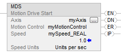
Examples
Example 1
The Speed operand is a REAL tag and Speed Units is "Units per sec"
Ladder Diagram
Structured Text
MDS(myAxis,myMotionControl,mySpeed_REAL,Unitspersec);
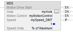
Example 2
The Speed operand is a DINT tag and Speed Units is % of Maximum
Ladder Diagram
Structured Text
MDS(myAxis,myMotionControl,mySpeed_DINT,%ofMaximum);
Example 3
Relay Ladder
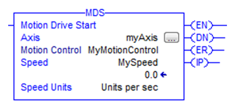
Structured Text
MDS(myAxis,MyMotionControl,MySpeed,Unitspersec);
Provide Feedback