Configure IP Address, BOOTP Setting, Port Speed and Duplex
To configure the IP address, BOOTP/DHCP setting, Port Speed and Duplex:
- Go online with the controller.
- In theController Organizer, right-click the module, and selectProperties.
- Select thePort Configurationtab.
- In the IP Address box, enter the IP address of the module on the network.addressA PLC-5/SLC term. File, element, and bit addresses (for example, N:7/0) no longer exist in ControlLogix. Instead, memory is allocated and named using tags.This value must match the IP address you entered on theGeneraltab. If this value is incorrect on theGeneraltab, and the Ethernet module sits on the network rather than in the local chassis, the controller cannot reach the module.If you reconfigure your Ethernet module with a different IP Address, you may lose communications with the module when you selectSet. To correct this problem, go to theGeneraltab, set the new IP address, and re-download to the controller.
- InSubnet Mask, enter the appropriate subnet mask of the module.subnet maskSubnet addressing is an extension of the IP address scheme that allows a site to use a single net ID for multiple physical networks. Routing outside of the site continues by dividing the IP address into a net ID and a host ID via the class. Inside a site, the subnet mask is used to redivide the IP address into a custom net ID portion and host ID portion. This field is set to 0.0.0.0 by default.For example, use Network 2, a Class B network, and add another physical network. Selecting the following subnet mask adds two additional net ID bits, allowing for four physical networks:11111111 11111111 11000000 00000000 = 255.255.192.0Two bits of the Class B host ID have been used to extend the net ID. Each unique combination of bits in the part of the host ID where subnet mask bits are 1 specifies a different physical network. The new configuration is:
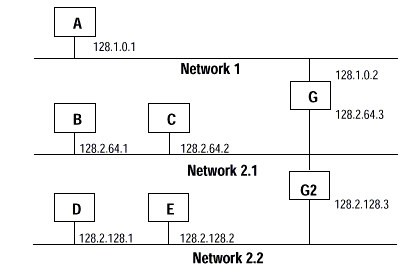 A second network with Hosts D and E has been added. Gateway G2 connects Network 2.1 with Network 2.2. Hosts D and E will use Gateway G2 to communicate with hosts not on Network 2.2. Hosts B and C will use Gateway G to communicate with hosts not on Network 2.1. When B is communicating with D, G (the configured Gateway for B) will route the data from B to D through G2.
 - InFactoryTalk Linx GatewayAddress, enter the appropriate address of the module.addressA PLC-5/SLC term. File, element, and bit addresses (for example, N:7/0) no longer exist in ControlLogix. Instead, memory is allocated and named using tags.
- InDomain Name, enter the appropriate domain name.domain nameThe domain name can have the following format:
- a.b.c.d
- a.b.c
- a.b
- a
where a, b, c, and d may contain only letters, digits, and hyphens. The total number of characters, including the ".", must be 48 or less. If you enter an invalid name, the software will not accept it and will display an error message.The portions of a domain name may be all numeric, except for the last portion. For example, you may have the following:- xyz.xxx.yyy.com
- 123.xxx.yyy.com
- 123.123.123.com
- 123.123.com
but NOT:- 123.123.123.123 (illegal)
- InHost Name, enter the appropriate host name.
- Enter the Primary DNS Server Address of the module.primary/secondary DNS server addressThis configuration option allows a server to accept a text-based address and perform a database lookup to convert that address to an IP address that can be used by the network. If a message uses a host name address, it must be converted somehow to an IP address before it can be sent to the destination controller. When the controller has a DNS server address configured, then the DNS server is used to take the host name address and convert it to the IP address of the destination module and the message can be sent. The two fields are set to 0.0.0.0 by default.Each octet of the IP address must be in the range of 0…255. The first octet cannot be 127 or greater than 223.
- Enter the Secondary DNS Server Address of the module.primary/secondary DNS server addressThis configuration option allows a server to accept a text-based address and perform a database lookup to convert that address to an IP address that can be used by the network. If a message uses a host name address, it must be converted somehow to an IP address before it can be sent to the destination controller. When the controller has a DNS server address configured, then the DNS server is used to take the host name address and convert it to the IP address of the destination module and the message can be sent. The two fields are set to 0.0.0.0 by default.Each octet of the IP address must be in the range of 0…255. The first octet cannot be 127 or greater than 223.
Provide Feedback