Nodes on an EtherNet/IP Network
When configuring your control system, you must account for the number of
EtherNet/IP™
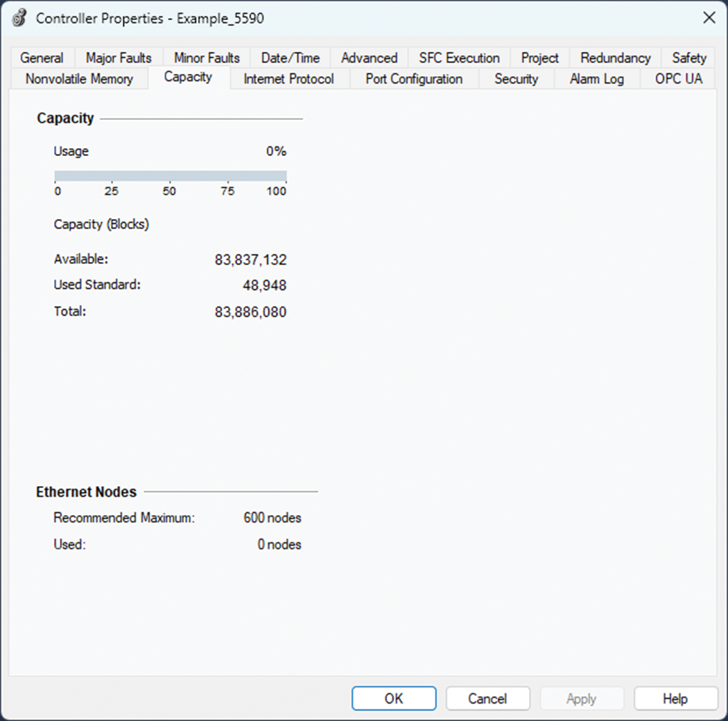
nodes you include in the I/O configuration tree in your project.Maximum Number of Ethernet Nodes
Devices Included in the Node Count
Any
EtherNet/IP™
devices that you add to the I/O configuration section are counted toward the controller node limits. The following are examples of devices that must be counted:- Remote communication adapters
- Remote controllers
- Devices with an embedded EtherNet/IP port
- EtherNet/IP™devices that are added to the I/O tree under a communication module in the local chassis, even though the communication module in the local chassis does not count as a node
- HMI devices that are added to the I/O tree
- Third-party devices that are directly connected to theEtherNet/IP™network
Devices Excluded from the Node Count
When considering the
EtherNet/IP™
node limitation of a controller, you do not count Ethernet devices that exist on the EtherNet/IP™
network but are not added to the I/O configuration section of the project. The following devices are not added to the I/O configuration section in your project and are not counted among the total number of nodes:
- Computer
- Communication modules in the local chassis
- HMIs that are not added to the I/O configuration section
- Devices that are the target of MSG Instructions
- Standard Ethernet devices with which the controller communicates via a socket interface
The following example shows five nodes in the I/O tree.
Ethernet Nodes Example
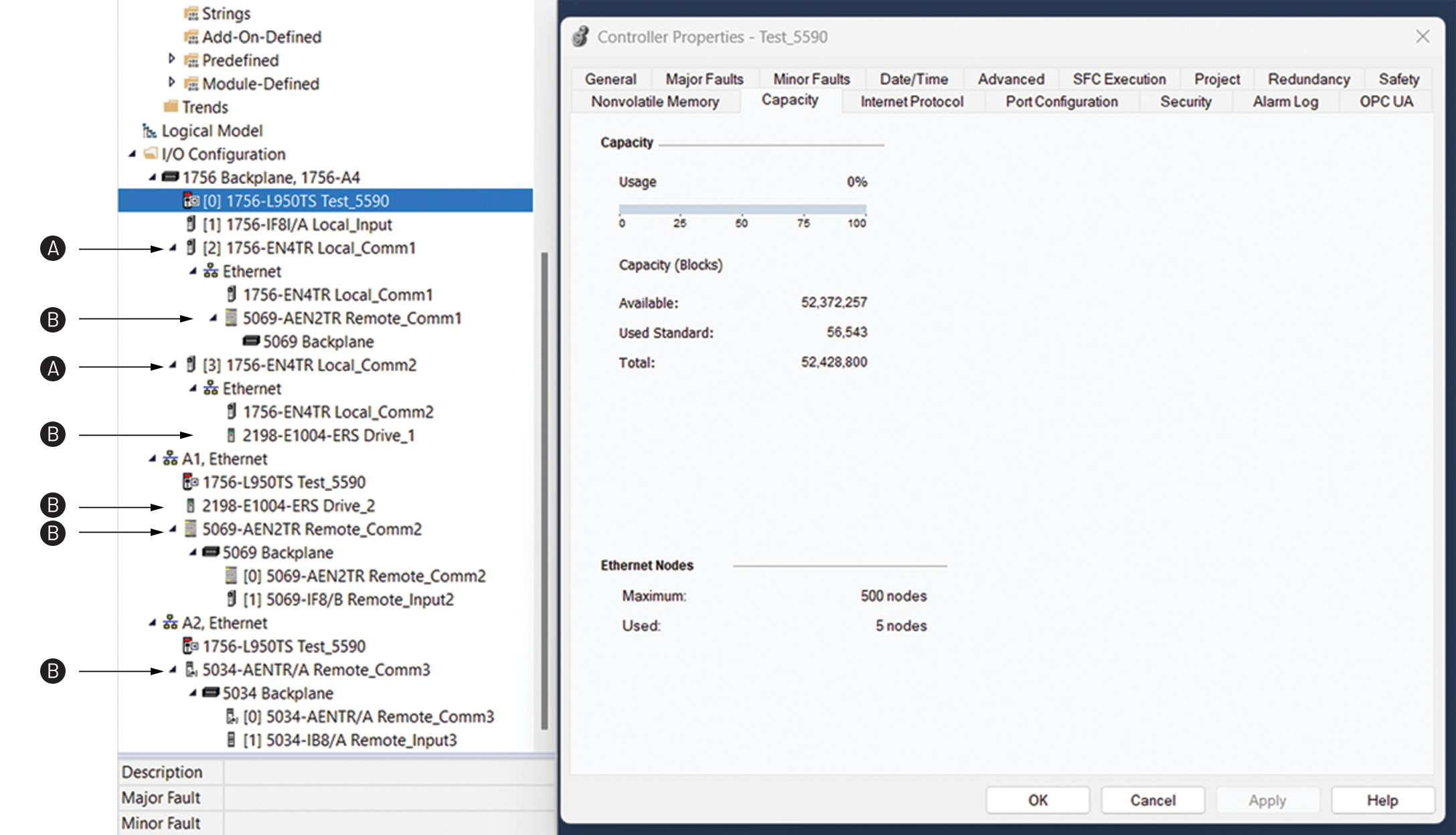
Item | Description |
|---|---|
A | Not a node. Module is in the local chassis. |
B | Node |
Provide Feedback