
Surge Suppressors
This chapter provides information on the use of surge suppressors to protect the relay
output contacts of the relay output module when switching inductive loads. It also
describes recommended surge suppressors for AC and DC load applications.
Because of the potentially high current surges that occur when switching inductive load
devices, such as motor starters and solenoids, the use of some type of surge suppression
to protect and extend the operating life of the I/O module's output contacts is
required. Switching inductive loads without surge suppression can significantly reduce
the life expectancy of relay contacts. By adding a suppression device directly across
the coil of an inductive device, you prolong the life of the output or relay contacts.
You also reduce the effects of voltage transients and electrical noise from radiating
into adjacent systems.
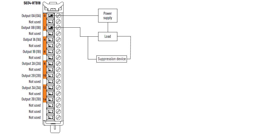
The following figure shows an output with a suppression device for the 5034-OW4I relay
output module. We recommend that you locate the suppression device as close as possible
to the inductive load device.
5034-OW4I Relay Output Module with a Suppression Device
For DC outputs driving inductive loads, use an appropriate diode for surge suppression.
These surge suppression circuits can be connected directly across the load device.
Suitable surge suppression methods for inductive AC load devices include a varistor, an
RC network, or an Allen-Bradley® surge suppressor, as shown in the following figure.
These components must be appropriately rated to suppress the switching transient
characteristic of the particular inductive device. See Table 1 for recommended devices.
Surge Suppression for Inductive AC Load Devices

Recommended Surge Suppressors
Use the Allen-Bradley surge suppressors shown in the table below with relays,
contactors, and starters.
Device | Coil Voltage (Original) | Suppressor Catalog Number | Type (1) |
|---|---|---|---|
Bulletin 100/104K 700K | 24…48V AC | 100-KFSC50 | Resistor Capacitor (RC) |
110…280V AC (5) | 100-KFSC280 | ||
12…55V AC | 100-KFSV55 | Metal Oxide Varistor (MOV) | |
12…77V DC | |||
56…136V AC | 100-KFSV136 | ||
78…180V DC (5) | |||
137…277V AC (5) | 100-KFSV277 | ||
12…250V DC (5) | 100-KFSD250 | Diode | |
Bulletin 100C (C09…C97) | 24…48V AC | 100-FSC48 (2) | RC |
110…280V AC (5) | 100-FSC280 (1) | ||
12…55V AC | 100-FSV55 (1) | MOV | |
12…77V DC | |||
56…136V AC | 100-FSV136 (1) | ||
78…180V DC (5) | |||
137…277V AC (5) | 100-FSV277 (1) | ||
12…250V DC (5) | 100-FSD250 (1) | Diode | |
Bulletin 509 Motor Starter Size 0...5 | 12…120V AC | 599-K04 | MOV |
240…264V AC (5) | 599-KA04 | ||
Bulletin 509 Motor Starter Size 6 | 12…120V AC | 199-FSMA1 (3) | RC |
12…120V AC | 199-GSMA1 (4) | MOV | |
Bulletin 700 R/RM Relay | AC coil | Not required | – |
24…48V DC | 199-FSMA9 | MOV | |
50…120V DC | 199-FSMA10 | ||
Bulletin 700 Type N, P, PK, or PH Relay | 6…150V AC/DC (5) | 700-N24 | RC |
24…48V AC/DC | 199-FSMA9 | MOV | |
50…120V AC/DC | 199-FSMA10 | ||
130…250V AC/DC (5) | 199-FSMA11 | ||
6…300V DC (5) | 199-FSMZ-1 | Diode | |
Miscellaneous electromagnetic devices limited to 35 sealed
VA | 6…150V AC/DC (5) | 700-N24 | RC |
(1) Do not use RC Type with Triac outputs. Varistor is not
recommended for use on the relay outputs. (2) Catalog numbers for screwless terminals include the
string 'CR' after '100-'. For example: Catalog number
100-FSC48 becomes 100-CRFSC48; Catalog number 100-FSV55
becomes 100-CRFSV55; and so on. (3) For use on the interposing relay. (4) For use on the contactor or starter. (5) For contact ratings, see the PointMax I/O System
Specifications Technical Data, publication 5034-TD001. | |||
Provide Feedback