
Connect Power to Adapter
Before you connect an external power source to the 5034-RTB6 or 5034-RTB6S terminals, make
sure that the power source is properly sized. For example, if the total module power current
draw, including current inrush requirements, is 4 A, you can use a power supply that is
limited to 4 A.
- Verify that the external power supply is not powered.
- Strip insulation from the wires that you connect to the 5034-RTB6 or 5034-RTB6S.
- Use a small terminal block screwdriver with a hardened 3 mm (0.11 in.) diameter blade such as Allen-Bradley catalog number 1492-N90.
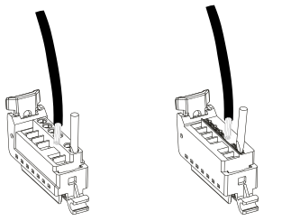
- For a screw-type RTB, proceed as follows:
- Insert the stranded wire into the wire cage.
- Tighten the screw to the torque specified in PointMax I/O System Specifications Technical Data, publication 5034-TD001.
- For a spring-type RTB, proceed as follows:
- Insert a screwdriver into the pusher slot to open the wire cage.
- Insert the stranded wire into the wire cage.
Wire Specifications - 1-wireWire TypeWire Size RangeStrip Length Tolerance (± 0.4mm)Screw RTB/Spring RTBSolid and Stranded Copper0.34…1.5 mm2(22…16 AWG)10 mm (0.39 in.)
Provide Feedback