Loading
Innovation Center LOGO
Recent ActivityRecent Activity

PID Control System Emulation for Industrial Variables

The application of a PID control system is a highly useful tool for industrial control and automation teams, enabling critical testing of key variables, systems, and processes. - [Implementation time: 60 minutes]
Innovation Center Home Page
Right-facing view of Allen-Bradley Micro870 controller catalog 2080-LC70-24QWB
Innovation Center LOGO
  • Overview
  • Installation Guide
  • Downloads
  • Contact us
  • I want to subscribe.
Innovation Center Home Page


What is this for?

The purpose of this PID control system emulation application is to simulate a first-order system in the Laplace domain alongside a PID controller, enabling testing and analysis of the behavior of a variable to be controlled within a plant.

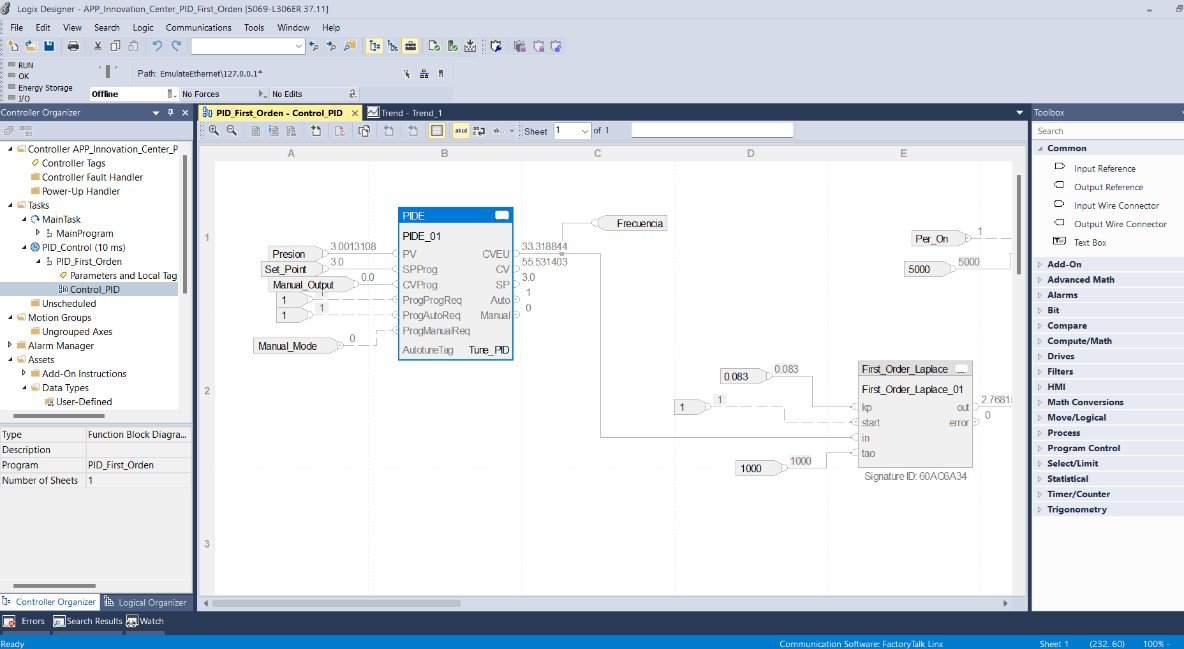
The application was developed in the Studio 5000 Logix Designer environment using Function Block language. It includes the emulation of a first-order system in the Laplace domain, its PID controller, and a disturbance environment. These components are considered the main criteria for testing control of key variables in industrial environments.

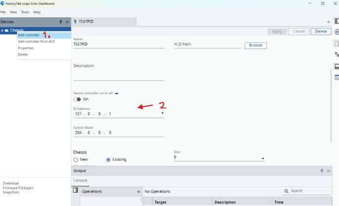
This application offers the option to operate digitally via FT Logix Echo or, alternatively, connect to a PC/Laptop and download the program to a physical controller available to the user. In this first version, the key focus is on monitoring through the graphs generated by the emulation, which display the control and process variables the user wishes to work with.


Is this useful for me?

Many industrial variables behave similarly to the system modeled in this application: Temperature, Pressure (used in the explanation and example), Speed, Level, etc. Modeling these first-order systems is practical due to their mathematical simplicity (which facilitates PID controller design), acceptable approximation tolerance, and ease of identifying parameters and coefficients.

This application has become a highly useful tool for plant control and automation teams, integrators, and other stakeholders in industrial control systems. It allows for relevant testing to determine the best way to control key variables, such as identifying how long it takes for a plant to stabilize based on the variables of each process. All of this can be done prior to on-site testing and system commissioning.

This type of application is important because users can build and adjust it to become a practical technological training tool for use with their own teams, and as a testing environment for technical concept validations that support future project development.


Downloads

Please note: You will need to agree to the Terms & Conditions for each download.

Downloadable file ›
Legal Disclaimer Acceptance. ROCKWELL AUTOMATION WILL PROVIDE ACCESS TO ROCKWELL PRODUCTS (BEST PRACTICES, APPLICATIONS AND KNOWLEDGE) ON THE CONDITION THAT YOU ACCEPT AND COMPLY WITH THE FOLLOWING TERMS AND CONDITIONS. YOU ACCEPT AND AGREE TO BE BOUND BY THE TERMS OF THIS AGREEMENT BY DOWNLOADING, INSTALLING, COPYING, OR OTHERWISE USING PRODUCTS. IF YOU ARE ACCEPTING THESE TERMS ON BEHALF OF ANOTHER PERSON, COMPANY, OR OTHER LEGAL ENTITY, YOU REPRESENT AND WARRANT THAT YOU HAVE FULL AUTHORITY TO BIND THAT PERSON, COMPANY, OR LEGAL ENTITY TO THESE TERMS. IF YOU DO NOT AGREE TO THESE TERMS, DO NOT DOWNLOAD, INSTALL, COPY, ACCESS, OR USE THE PRODUCTS, SOFTWARE AND/OR CLOUD SERVICES. 1. Rockwell Automation retains full ownership and title to all Products and related documentation. No rights or licenses are granted other than those set forth in this Agreement. Company grants to Rockwell Automation a non-exclusive, worldwide, royalty-free, perpetual, non-revocable license to use any feedback Company provides regarding the Products, even if Company has designated the feedback as confidential. Rockwell Automation will be entitled to use the feedback without restriction or compensation to Company. 2. Company may not lease sub-lease, assign, license, sub-license or otherwise transfer any of the Products without the prior written consent of Rockwell Automation. Company may not assign or otherwise transfer access rights to the Products without the prior written consent of Rockwell Automation. Any reverse assembly, reverse engineering, decompilation, and creation of derivative works based on the Products by Company is prohibited. 3. Company acknowledges that Products provided under this Agreement are Rockwell Automation’s Confidential Information and are covered by effective or pending copyrights, patents, trademarks and/or trade secrets of Rockwell Automation, and Company agrees to maintain confidentiality by not disclosing Products or documentation to any third party without the prior written consent of Rockwell Automation and to protect the confidentiality of the Products as it would Company’s own confidential information. Company agrees that its obligation of confidentiality under this paragraph shall survive expiration or termination of this Agreement. 4. Company agrees that Products provided under this Agreement are prototypes and examples and its application and results may vary depending on each customer and project conditions. Rockwell Automation do not warranty the same results. This Agreement shall in no way be construed as a commitment by Rockwell Automation at any time to manufacture and/or offer Products for sale. There is no explicit or implicit service level agreement associated with using the Products. Rockwell Automation does not warrant that the functions contained in the Products will meet Company’s requirements. Company agrees to use all Products only in accordance with the instructions and only for the intended usages identified in the documentation. 5. EXCLUSION OF WARRANTIES AND LIMITATION OF LIABILITY. THE PRODUCTS ARE PROVIDED "AS IS". ROCKWELL AUTOMATION DISCLAIMS ANY AND ALL WARRANTIES, EXPRESS, IMPLIED OR STATUTORY, INCLUDING WITHOUT LIMITATION ANY WARRANTIES OF MERCHANTABILITY OR FITNESS FOR A PARTICULAR PURPOSE. ROCKWELL AUTOMATION EXPLICITLY DISCLAIMS ALL WARRANTIES OF NON- INFRINGEMENT AND EXPRESSLY DOES NOT WARRANT THAT THE PRODUCTS, IN WHOLE OR IN PART, WILL BE ERROR FREE OR FREE FROM SECURITY VULNERABILITIES. IN NO EVENT SHALL ROCKWELL AUTOMATION BE LIABLE FOR (i) LOST PROFITS, LOST SAVINGS, DOWNTIME, SPECIAL, INDIRECT OR CONSEQUENTIAL DAMAGES OF ANY KIND, OR (ii) ANY PERSONAL INJURY, PROPERTY DAMAGE OR ENVIRONMENTAL DAMAGE ARISING OUT OF OR IN CONNECTION WITH THIS AGREEMENT, WHETHER IN AN ACTION IN CONTRACT, STRICT LIABILITY OR IN TORT INCLUDING NEGLIGENCE. 6. COMPANY AGREES TO INDEMNIFY AND HOLD ROCKWELL AUTOMATION HARMLESS FROM ALL COSTS, AWARDS, DAMAGES, EXPENSES AND FEES (INCLUDING ATTORNEYS FEES) RESULTING FROM OR RELATED TO ANY THIRD-PARTY CLAIMS (INCLUDING EMPLOYEES AND AGENTS OF COMPANY) AGAINST ROCKWELL AUTOMATION, ITS DISTRIBUTORS, AGENTS, OFFICERS, DIRECTORS OR EMPLOYEES FOR PERSONAL INJURY (INCLUDING DEATH), PROPERTY DAMAGE OR ENVIRONMENTAL DAMAGE RELATED TO OR RESULTING FROM THE USE OF THE PRODUCTS. 7. In the event a Product is exported, Company agrees to comply with all applicable United States Export Control Law and Regulations, and the applicable export control laws of other countries. This Agreement shall be governed by the laws of the state of Wisconsin. This Agreement is the complete and exclusive Agreement between Rockwell Automation and the Company, and supersedes all prior agreements, whether written or oral, relating to the Products.


Need Help?

If you need help with an application or have feedback from the Innovation Center, please contact us.


How can I make it work?

Requirements: products, tools, prior knowledge.

Hardware & Software


Requirements Version
1 Studio 5000 Logix Designer 37.01 or higher
2 FactoryTalk Logix Echo 3.00 or higher
3 OPTIONAL - Rockwell Controller (CompactLogix,ControlLogix) 
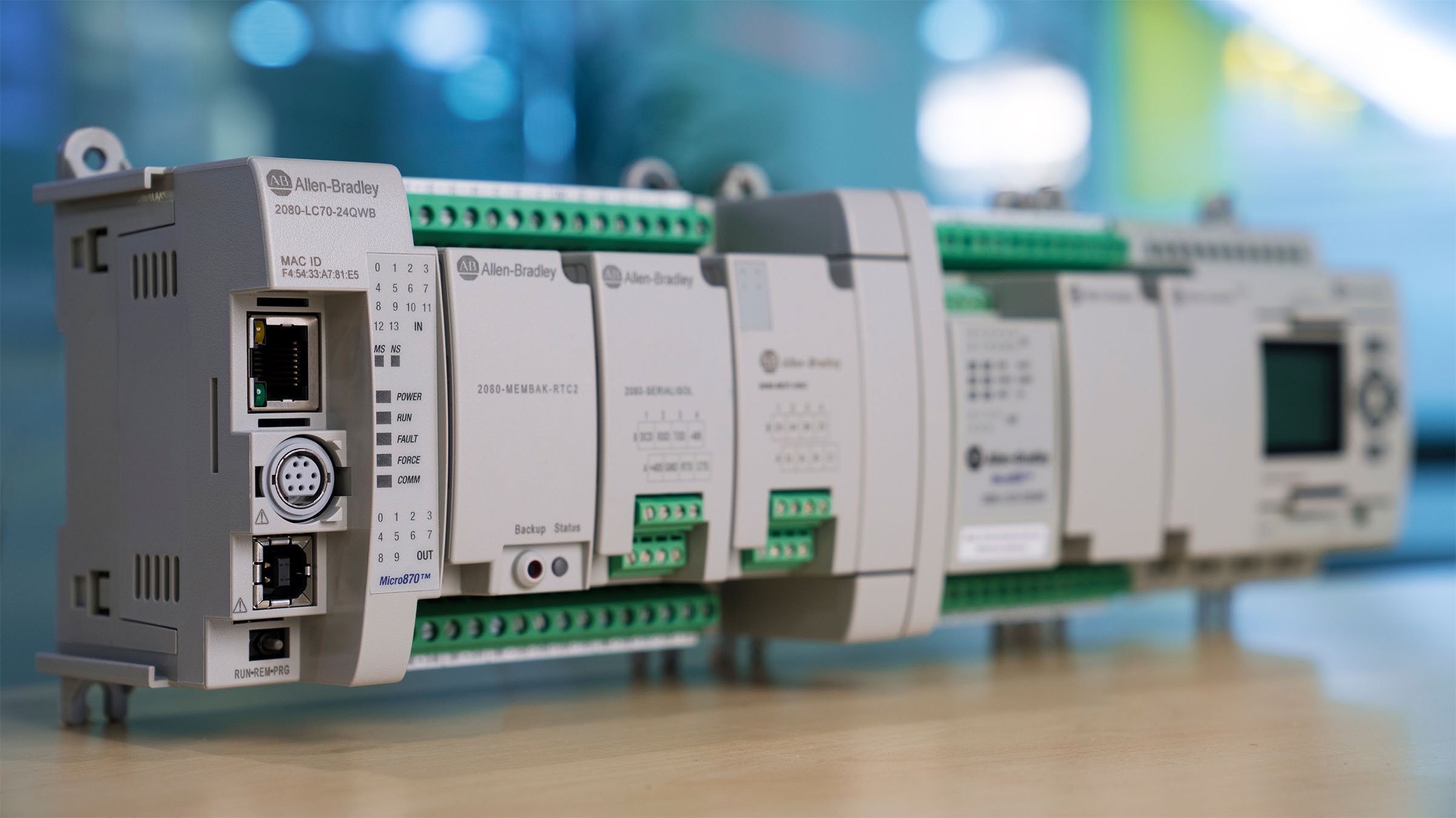
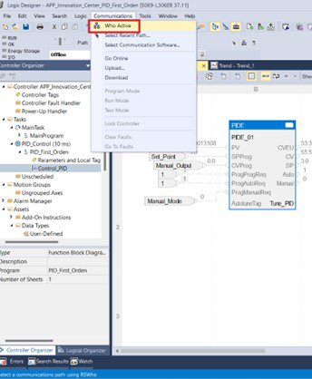
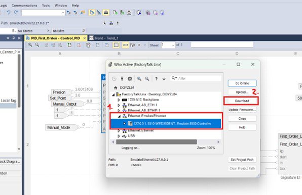
The system can be tested with a Rockwell controller connected to the Studio 5000 programming environment.


Practical Knowledge Required

  • Basic programming and configuration skills in Studio 5000 Logix Designer and FT Logix Echo, and understanding of Allen-Bradley controller functionality and parameterization.


Theoretical Knowledge Required

  • First-Order Systems in the Laplace Domain

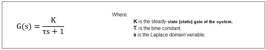
A typical first-order system has a transfer function of the form:

pid-control-system-emulation-for-industrial-variables_formula1_EN.jpg

This type of system responds exponentially to a step input, without oscillations, and with a single time constant.
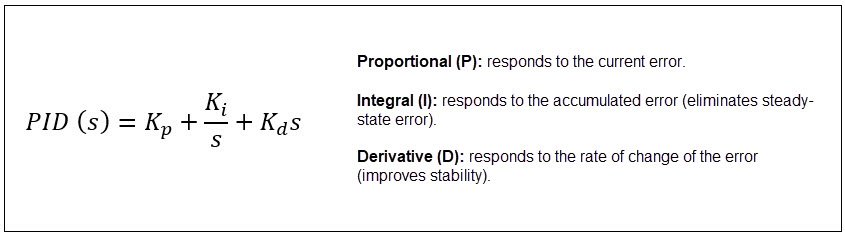
  • PID Controller

The PID controller consists of three components:

pid-control-system-emulation-for-industrial-variables_formula2_EN.jpg
  • How the PID and First-Order System Interact

When a PID controller is connected to a first-order system, the goal is to modify the system's response to meet specific performance criteria, such as:

Faster response time
Reduced overshoot
Elimination of steady-state error

The closed-loop transfer function becomes:

pid-control-system-emulation-for-industrial-variables_formula3.jpg
 

Links of Interest (internal or external) - Function Block Properties Dialog Box - General Configuration Tab Overview (PIDE)


AHIC STEP ICON.png

Implementation Guide

 
  1. Step 1
  2. Step 2
  3. Step 3
  4. Step 4
Open All Close All
Step 1
 

Step 1: Enable the Emulated Controller in FT Logix Echo

(Optional) Connect the controller to your PC/Laptop. 


Add the controller and assign it and IP address for proper connection within the Studio 5000 environment.

 
pid-control-system-emulation-for-industrial-variables_Picture1.jpg

pid-control-system-emulation-for-industrial-variables_Picture1

Step 2
 

Step 2


1 - Download the file à APP_Innovation_Center_PID_First_Orden.ACD


2 - Open it in Studio 5000 Logix Designer     


pid-control-system-emulation-for-industrial-variables_Picture2.jpg

pid-control-system-emulation-for-industrial-variables_Picture2


3 - Point your Project/program to the controller started in FT Logix Echo

  • Identify it using the “Who Active” function in Studio 5000
 
pid-control-system-emulation-for-industrial-variables_Picture3.jpg

pid-control-system-emulation-for-industrial-variables_Picture3

 
  • Establish the correct connection with the emulated controller and download the program to the respective controller
 
pid-control-system-emulation-for-industrial-variables_Picture4.jpg

pid-control-system-emulation-for-industrial-variables_Picture4

Step 3
 

Step 3: Validate Functional Blocks and Understand their use

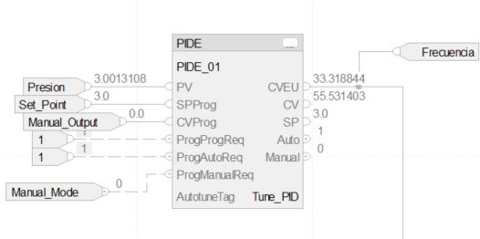
  • In the current example, a plant and its control system are emulated. The two key process variables are:

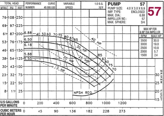
    Pressure – Process Variable (e.g., managed via a pump) together with a control system led by the Allen-Bradley controller (ControlLogix) in addition to another device that works based on the next variable.

    Frequency – Control Variable (e.g., managed via a variable frequency drive – VFD)  

    In summary, the system controls a pump using frequency adjustments from the drive to stabilize the pressure level.

     
    pid-control-system-emulation-for-industrial-variables_formula4.jpg
     

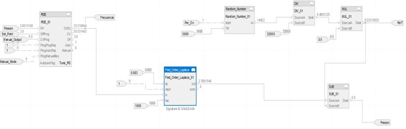
    The program system consists of three fundamental parts:

    • Bloque First Order Laplace
     
    pid-control-system-emulation-for-industrial-variables_Picture5.jpg

    pid-control-system-emulation-for-industrial-variables_Picture5


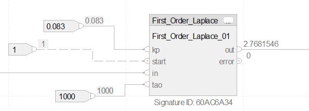
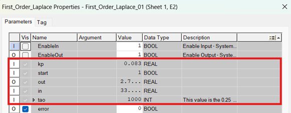
    This block simulates the behavior of a first-order linear system in the Laplace domain, representing the pressure variable. It follows the equation described earlier in the documentation.

     
    pid-control-system-emulation-for-industrial-variables_Picture6.jpg

    pid-control-system-emulation-for-industrial-variables_Picture6

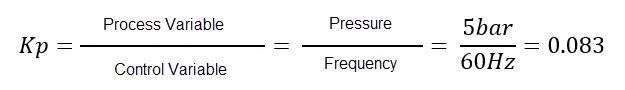
  • The variables shown in the graph must be defined in this block: the system’s static gain (Kp) and the time constant (τ) are based on previously estimated values.


    For example, τ = 1000 ms corresponds to the approximate stabilization time of the first-order system. Functionally, we can estimate the system’s static gain:

     
    pid-control-system-emulation-for-industrial-variables_formula5_EN.jpg

    pid-control-system-emulation-for-industrial-variables_formula5.jpg


    In: Defined by the control system’s output frequency, which enters this block.


    Out: The output pressure variable, which interacts with system disturbances before returning to the PID controller.

     
    pid-control-system-emulation-for-industrial-variables_Picture7.jpg

    pid-control-system-emulation-for-industrial-variables_Picture7.jpg

     
    • Disturbance Block
       
    pid-control-system-emulation-for-industrial-variables_Picture8.jpg

    pid-control-system-emulation-for-industrial-variables_Picture8.jpg

     
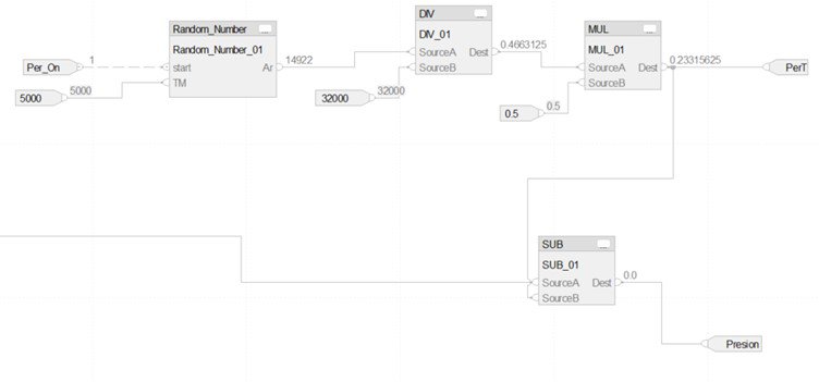
  • This segment includes several mathematical function blocks to simulate a disturbing environment.

    In the diagram, four blocks are shown:

    • Random Number: Generates a random value from 0 to 32000 every 5 seconds, simulating periodic disturbances.
    • DIV and MUL: Convert the random value to a percentage and scale it to the defined maximum disturbance (e.g., 5 bar or 0.5).
    • SUB (Subtract): Represents the effect of the disturbance on the pressure output from the pump. The output of this block becomes the feedback signal that closes the loop and enters the PID controller.


    • PID Controller Block
    pid-control-system-emulation-for-industrial-variables_Picture9.jpg

    pid-control-system-emulation-for-industrial-variables_Picture9

  • This block performs system control using a PID function block. Proper configuration of this block is essential for the application’s success.


    • Main Input Variables
      • PV (Process Value): Final pressure output after disturbance interaction.
      • SPProg (Set Point): Desired pressure level.
      • CVProg (Control Variable): Used in manual mode to define the frequency for observing system behavior.
      • ProgProgReq: Enables automatic mode (set to bit “1”).
      • ProgManualReq: Enables manual mode (set to bit “1”); other modes must be set to “0”.


    • Main Output Variables
    • CV: Percentage output used in manual mode.
    • CVEU: Final control variable value (frequency), which feeds into the Laplace block.
     
  • Once inside the PID block properties, we configure the control block to ensure proper system response. 

     
    pid-control-system-emulation-for-industrial-variables_Picture10.jpg

    pid-control-system-emulation-for-industrial-variables_Picture10


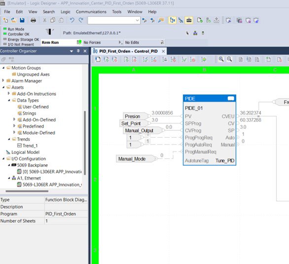
    The first time the PID control block is used, it is necessary to perform the Autotune process (this procedure must be executed in Run Mode – controller), as it is essential for calculating the system gains (which have not been previously configured – in the image they were disabled for explanation purposes) and other parameters of the control block that will later operate in automatic mode (ProgProgReq=1).

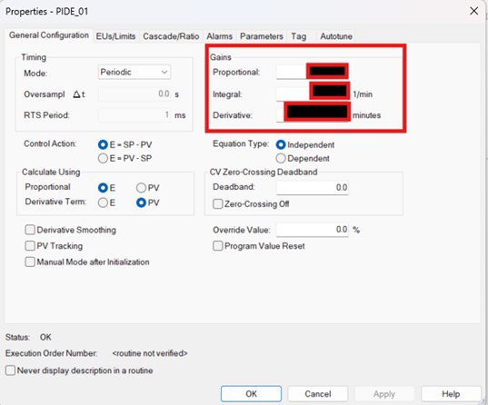
    To initiate this, access the block’s properties (Properties – previous image) and begin selecting the appropriate settings according to the specific conditions of the application

  • The first relevant configuration is the Timing Mode (1), which should be set to periodic, as recommended, due to the nature of the task execution. Next is the Control Action (2); in this case, since the control behavior corresponds to a direct action, the first of the two available options should be selected. Finally, the last choice concerns how the process variable is calculated (3); the selected option corresponds to the typical configuration for this type of integral systems.


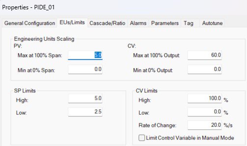
    The next tab within the Properties window is EUs Limits, where the operating ranges of the system’s key variables must be defined: PV (Process Variable) – pressure in our case, and CV (Control Variable) – frequency in our case. According to the parameters previously mentioned in the documentation, the maximum pressure value is defined as 5 bar, and the maximum frequency value is 60 Hz. Subsequently, the limits for the control variable (CV) are configured, and the rate of change refers to the percentage of controller output segmented according to the defined step intervals


    pid-control-system-emulation-for-industrial-variables_Picture11.jpg

    pid-control-system-emulation-for-industrial-variables_Picture11.jpg

    pid-control-system-emulation-for-industrial-variables_Picture11B.jpg

    pid-control-system-emulation-for-industrial-variables_Picture11b.jpg

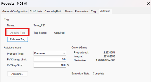
  • Finally, for the Autotune process, we navigate to the tab with the same name, where a Tag must be acquired (this is required when performing the process for the first time). Once the Tag is acquired, we proceed to define the Autotune inputs, starting with the variable type (Pressure), the maximum limit for the process variable change, and lastly, the size of the unit step increments that the control process will use.


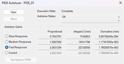
    To complete the gain calculation, we proceed by clicking the Autotune button. It is important to note that the PID module must be in Manual Mode for the Autotune to execute properly. Upon completion, the module must be switched to Auto Mode to begin operation, which is controlled via the Manual_Mode Tag.

     
    pid-control-system-emulation-for-industrial-variables_Picture12.jpg

    pid-control-system-emulation-for-industrial-variables_Picture12.jpg


    To calculate the gains, simply press the “Start” button. The program will compute the gains based on three response types (Slow, Medium, Fast), from which one must be selected according to the control system requirements. These gains are then applied to the control system using the “Set Gains in PIDE” button. The idea is that, by observing the graphical response displayed in Studio 5000, the user can identify which of the calculated gain response types is most suitable for the emulated system.


    If additional information or functional explanations are required for the programming blocks used in the application program, the respective “Help” sections for each block can be consulted, such as the one shared in the “Links of Interest” section of this documentation.

Step 4
 

Step 4: Tests & Application running

  •  
    pid-control-system-emulation-for-industrial-variables_Picture13.jpg

    pid-control-system-emulation-for-industrial-variables_Picture13


    As previously mentioned, to perform the final changes and adjustments (Autotune), the system must be operating in “Remote Run” mode within Studio 5000. Once this is set, the overall system will be fully operational, allowing for verification of the control system’s response to the entire structure that comprises it, including disturbances.

    pid-control-system-emulation-for-industrial-variables_Picture14.jpg

    pid-control-system-emulation-for-industrial-variables_Picture14

    pid-control-system-emulation-for-industrial-variables_Picture15.jpg

    pid-control-system-emulation-for-industrial-variables_Picture15


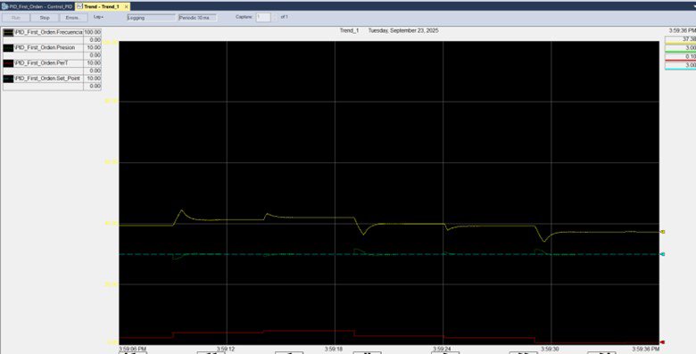
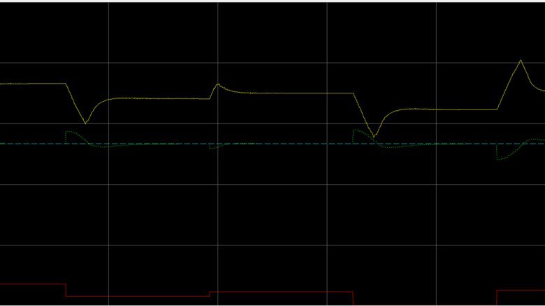
    By executing the “Run” command, the system response can be visualized through a graph displaying the four most important curves: Yellow (Frequency), Green (Pressure), Red (Disturbances), and Blue (Controller-defined Set Point)

  •  
    pid-control-system-emulation-for-industrial-variables_Picture16.jpg

    pid-control-system-emulation-for-industrial-variables_Picture16

    This graphical representation allows us to identify key behaviors of the system, enabling the emulation and analysis of the control process and its response to various scenarios that may arise. This is ideal for the intended purpose—creating test scenarios prior to implementation in the actual plant, allowing for adjustments and potentially significant improvements. In the highlighted area within the orange box, the graph focuses on a time period during which the system experiences disturbances. It shows how the “drive” adjusts the frequency to stabilize the system, and how the process variable, “pressure,” gradually aligns with the control target (set point – blue curve). Throughout the graphed time frame, we observe variations in disturbances and corresponding changes in each response curve, including adjustments, overshoots, and other typical behaviors of industrial systems with this type of variable—commonly modeled as first-order linear systems in the Laplace domain.


    It is important to note that the example implemented in the application was designed to emulate a control process involving a pump, working in conjunction with a drive and motor as the control elements. However, the application is structured in such a way that, as explained earlier, it can emulate scenarios involving other industrial variables that behave similarly in first-order systems, such as Level, Temperature, Speed, etc. All necessary adjustments depending on the situation can be applied within the PID control block, as detailed throughout the documentation.


pid-control-system-emulation-for-industrial-variables_Picture1.jpg

pid-control-system-emulation-for-industrial-variables_Picture1.jpg

pid-control-system-emulation-for-industrial-variables_Picture2.jpg

pid-control-system-emulation-for-industrial-variables_Picture2.jpg

pid-control-system-emulation-for-industrial-variables_Picture3.jpg

pid-control-system-emulation-for-industrial-variables_Picture3.jpg

pid-control-system-emulation-for-industrial-variables_Picture4.jpg

pid-control-system-emulation-for-industrial-variables_Picture4.jpg

pid-control-system-emulation-for-industrial-variables_Picture5.jpg

pid-control-system-emulation-for-industrial-variables_Picture5.jpg

pid-control-system-emulation-for-industrial-variables_Picture6.jpg

pid-control-system-emulation-for-industrial-variables_Picture6.jpg

pid-control-system-emulation-for-industrial-variables_Picture7.jpg

pid-control-system-emulation-for-industrial-variables_Picture7.jpg

pid-control-system-emulation-for-industrial-variables_Picture8.jpg

pid-control-system-emulation-for-industrial-variables_Picture8.jpg

pid-control-system-emulation-for-industrial-variables_Picture9.jpg

pid-control-system-emulation-for-industrial-variables_Picture9.jpg

pid-control-system-emulation-for-industrial-variables_Picture10.jpg

pid-control-system-emulation-for-industrial-variables_Picture10.jpg

pid-control-system-emulation-for-industrial-variables_Picture11.jpg

pid-control-system-emulation-for-industrial-variables_Picture11.jpg

pid-control-system-emulation-for-industrial-variables_Picture11B.jpg

pid-control-system-emulation-for-industrial-variables_Picture11B.jpg

pid-control-system-emulation-for-industrial-variables_Picture12.jpg

pid-control-system-emulation-for-industrial-variables_Picture12.jpg

pid-control-system-emulation-for-industrial-variables_Picture13.jpg

pid-control-system-emulation-for-industrial-variables_Picture13.jpg

pid-control-system-emulation-for-industrial-variables_Picture14.jpg

pid-control-system-emulation-for-industrial-variables_Picture14.jpg

pid-control-system-emulation-for-industrial-variables_Picture15.jpg

pid-control-system-emulation-for-industrial-variables_Picture15.jpg

pid-control-system-emulation-for-industrial-variables_Picture16.jpg

pid-control-system-emulation-for-industrial-variables_Picture16.jpg


PID Control System Emulation for Industrial Variables

Versión 1.2 - Mayo de 2026


AHIC White Logo
Subscribe!

Receive new app releases and other updates from the Innovation Center directly in your inbox.

I want to subscribe.
 
  1. Chevron LeftChevron Left Rockwell Automation Home
  2. Chevron LeftChevron Left Sup...
  3. Chevron LeftChevron Left Pro...
  4. Chevron LeftChevron Left Downloads
  5. Chevron LeftChevron Left Innovation Center
  6. Chevron LeftChevron Left PID Control System Emulation for Industrial Variables
Please update your cookie preferences to continue.
This feature requires cookies to enhance your experience. Please update your preferences to allow for these cookies:
  • Social Media Cookies
  • Functional Cookies
  • Performance Cookies
  • Marketing Cookies
  • All Cookies
You can update your preferences at any time. For more information please see our {0} Privacy Policy
CloseClose