Loading
Innovation Center LOGO
Recent ActivityRecent Activity

Multibelt Conveyor Control

Commission and run a synchronized three-train MultiBelt system while maintaining minimum separation through circular-distance control and position feedforward. - [Implementation Time: 30 Minutes]
Innovation Center Home Page
Cardboard boxes on automated conveyor belt in smart warehouse with digital logistics hologram concept.
Innovation Center LOGO
  • Overview
  • Implementation Guide
  • Download
  • Contact us
  • Subscribe
Innovation Center Home Page
 

What does this application do?

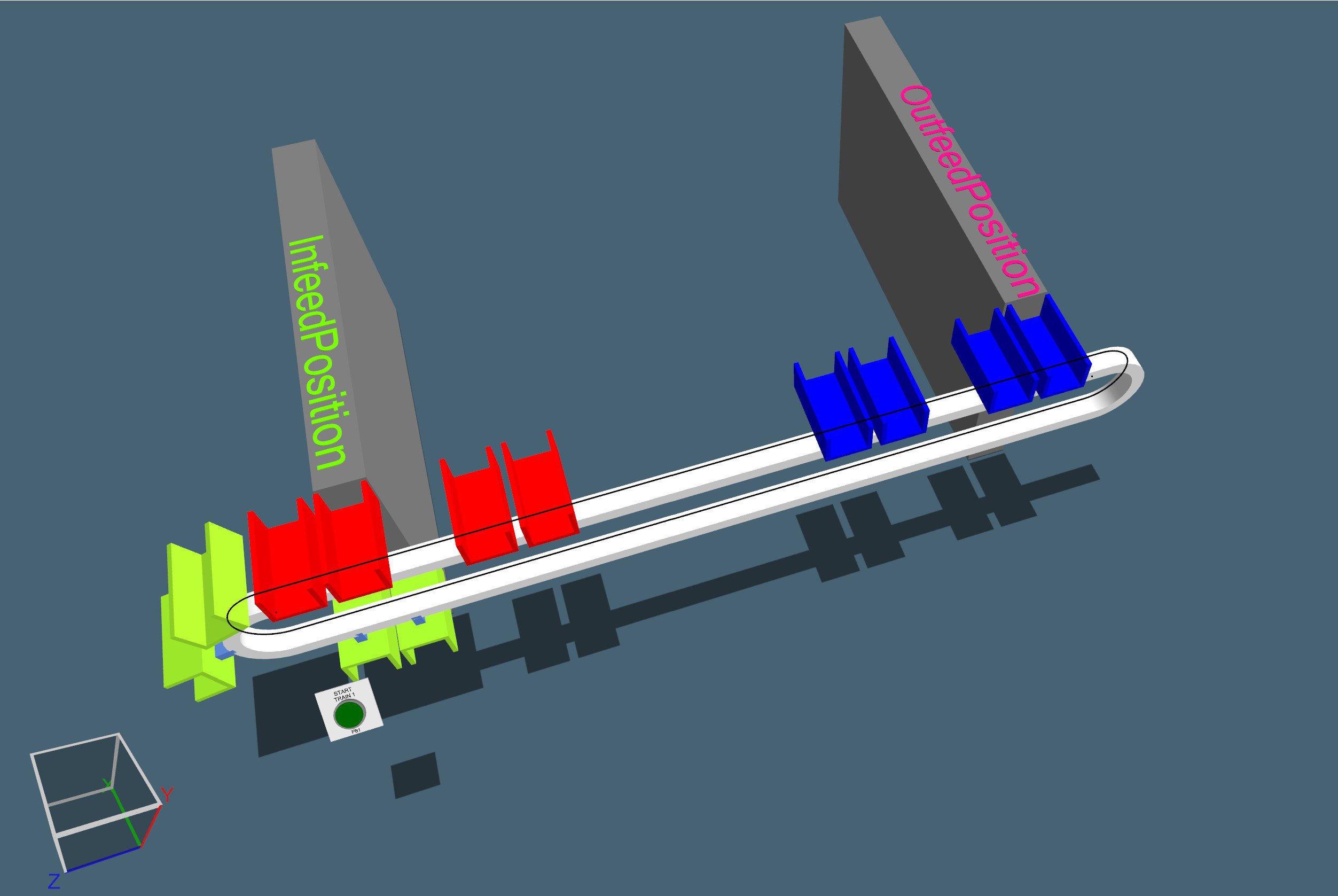
The project implements a motion control application for a MultiBelt system made up of three synchronized trains or carts on a circular path. Each train travels between a loading station and one or two unloading stations, keeping its distance from the preceding train to prevent collisions or approaches below a configured minimum distance.

The application runs on a GuardLogix/ControlLogix/CompactLogix controller and uses two main motion devices: Drive_1 and Drive_2. The train axes are named Ax_Train1, Ax_Train2 and Ax_Train3, and there is also an infeed belt axis called In_Belt along with the Ax_Converter axis, all grouped in the Axes motion group.

The logic is organized into three blocks. Main_Program governs the overall sequence: it initializes parameters and handles start-up, stop, fault reset, product simulation, MultiBelt coordination and axis management. Main_Motion_Prg executes the Q_MAM motion commands and publishes command positions for visualization or external integration. SafetyProgram manages the Safe Torque Off function of the trains through encoded safety AOIs.

The objective of this document is to commission the three-train MultiBelt application (or a configuration adapted to the need), run the cycle, observe the motion and stop it in a controlled way. The intended use mode is an environment that supports motion control, with a synchronized axis group, configured drives and a validated Safe Torque Off chain.

The problem it solves is the coordination of several independent movers on the same closed track. The logic prevents a train from catching up with the one ahead by calculating the circular distance between axes, applying a minimum distance, switching to queued mode when the gap shrinks, and propagating position feedforward from the preceding axis to the following train.


Limitations and Disadvantages

The application must not be operated on real equipment without a safety review, mechanical validation and authorization from the person responsible for the cell. Motion and safety functions must first be validated in a safe environment.

AHIC Download ICON VF.png

Downloads

Please note: You will need to agree to the Terms & Conditions for each download.

Downloadable file ›
Legal Disclaimer Acceptance. ROCKWELL AUTOMATION WILL PROVIDE ACCESS TO ROCKWELL PRODUCTS (BEST PRACTICES, APPLICATIONS AND KNOWLEDGE) ON THE CONDITION THAT YOU ACCEPT AND COMPLY WITH THE FOLLOWING TERMS AND CONDITIONS. YOU ACCEPT AND AGREE TO BE BOUND BY THE TERMS OF THIS AGREEMENT BY DOWNLOADING, INSTALLING, COPYING, OR OTHERWISE USING PRODUCTS. IF YOU ARE ACCEPTING THESE TERMS ON BEHALF OF ANOTHER PERSON, COMPANY, OR OTHER LEGAL ENTITY, YOU REPRESENT AND WARRANT THAT YOU HAVE FULL AUTHORITY TO BIND THAT PERSON, COMPANY, OR LEGAL ENTITY TO THESE TERMS. IF YOU DO NOT AGREE TO THESE TERMS, DO NOT DOWNLOAD, INSTALL, COPY, ACCESS, OR USE THE PRODUCTS, SOFTWARE AND/OR CLOUD SERVICES. 1. Rockwell Automation retains full ownership and title to all Products and related documentation. No rights or licenses are granted other than those set forth in this Agreement. Company grants to Rockwell Automation a non-exclusive, worldwide, royalty-free, perpetual, non-revocable license to use any feedback Company provides regarding the Products, even if Company has designated the feedback as confidential. Rockwell Automation will be entitled to use the feedback without restriction or compensation to Company. 2. Company may not lease sub-lease, assign, license, sub-license or otherwise transfer any of the Products without the prior written consent of Rockwell Automation. Company may not assign or otherwise transfer access rights to the Products without the prior written consent of Rockwell Automation. Any reverse assembly, reverse engineering, decompilation, and creation of derivative works based on the Products by Company is prohibited. 3. Company acknowledges that Products provided under this Agreement are Rockwell Automation’s Confidential Information and are covered by effective or pending copyrights, patents, trademarks and/or trade secrets of Rockwell Automation, and Company agrees to maintain confidentiality by not disclosing Products or documentation to any third party without the prior written consent of Rockwell Automation and to protect the confidentiality of the Products as it would Company’s own confidential information. Company agrees that its obligation of confidentiality under this paragraph shall survive expiration or termination of this Agreement. 4. Company agrees that Products provided under this Agreement are prototypes and examples and its application and results may vary depending on each customer and project conditions. Rockwell Automation do not warranty the same results. This Agreement shall in no way be construed as a commitment by Rockwell Automation at any time to manufacture and/or offer Products for sale. There is no explicit or implicit service level agreement associated with using the Products. Rockwell Automation does not warrant that the functions contained in the Products will meet Company’s requirements. Company agrees to use all Products only in accordance with the instructions and only for the intended usages identified in the documentation. 5. EXCLUSION OF WARRANTIES AND LIMITATION OF LIABILITY. THE PRODUCTS ARE PROVIDED "AS IS". ROCKWELL AUTOMATION DISCLAIMS ANY AND ALL WARRANTIES, EXPRESS, IMPLIED OR STATUTORY, INCLUDING WITHOUT LIMITATION ANY WARRANTIES OF MERCHANTABILITY OR FITNESS FOR A PARTICULAR PURPOSE. ROCKWELL AUTOMATION EXPLICITLY DISCLAIMS ALL WARRANTIES OF NON- INFRINGEMENT AND EXPRESSLY DOES NOT WARRANT THAT THE PRODUCTS, IN WHOLE OR IN PART, WILL BE ERROR FREE OR FREE FROM SECURITY VULNERABILITIES. IN NO EVENT SHALL ROCKWELL AUTOMATION BE LIABLE FOR (i) LOST PROFITS, LOST SAVINGS, DOWNTIME, SPECIAL, INDIRECT OR CONSEQUENTIAL DAMAGES OF ANY KIND, OR (ii) ANY PERSONAL INJURY, PROPERTY DAMAGE OR ENVIRONMENTAL DAMAGE ARISING OUT OF OR IN CONNECTION WITH THIS AGREEMENT, WHETHER IN AN ACTION IN CONTRACT, STRICT LIABILITY OR IN TORT INCLUDING NEGLIGENCE. 6. COMPANY AGREES TO INDEMNIFY AND HOLD ROCKWELL AUTOMATION HARMLESS FROM ALL COSTS, AWARDS, DAMAGES, EXPENSES AND FEES (INCLUDING ATTORNEYS FEES) RESULTING FROM OR RELATED TO ANY THIRD-PARTY CLAIMS (INCLUDING EMPLOYEES AND AGENTS OF COMPANY) AGAINST ROCKWELL AUTOMATION, ITS DISTRIBUTORS, AGENTS, OFFICERS, DIRECTORS OR EMPLOYEES FOR PERSONAL INJURY (INCLUDING DEATH), PROPERTY DAMAGE OR ENVIRONMENTAL DAMAGE RELATED TO OR RESULTING FROM THE USE OF THE PRODUCTS. 7. In the event a Product is exported, Company agrees to comply with all applicable United States Export Control Law and Regulations, and the applicable export control laws of other countries. This Agreement shall be governed by the laws of the state of Wisconsin. This Agreement is the complete and exclusive Agreement between Rockwell Automation and the Company, and supersedes all prior agreements, whether written or oral, relating to the Products.
AHIC NEED HELP ICON VF.png


Need Help?

If you need help with an application or have feedback from the Innovation Center, please contact us.


Is this application relevant to me?

It is useful for anyone who needs to understand, commission or demonstrate a conveying application with several coordinated carts in Studio 5000.


Application areas: Product conveying applications with independent carts or trains on a closed track, where each mover is loaded wagon by wagon at one station and unloaded at one or two downstream stations, and where a minimum separation between movers must be guaranteed. The project also serves as a demonstration of coordinated motion control and of integration with external visualization or simulation through the tags To_E3D_T1_CmdPos, To_E3D_T2_CmdPos and To_E3D_T3_CmdPos.


How can I make it work?

Requirements: products, tools, prior knowledge.

Hardware

  • 1756-L84ES controller or equivalent, major revision 36.
  • Kinetix 5700/5500/5300

Software

  • Studio 5000 Logix Designer version 36 or later, compatible with motion and safety projects.
  • Project file Q_MAM_P_v3_GL.acd.

Prior Knowledge

  • Programming in Studio 5000, CIP motion control (axis group, travel modes, position unwind and the MAM, MAJ, MAS and MRP instructions), use of Add-On Instructions, and basic understanding of safety applications with Safe Torque Off.


AHIC STEP ICON.png

Implementation Guide

 
  1. Step 1
  2. Step 2
  3. Step 3
  4. Step 4
  5. Step 5
  6. Step 6
  7. Step 7
  8. Step 8
  9. Step 9
  10. Step 10
  11. Step 11
  12. Step 12
  13. Step 13
  14. Step 14
  15. Step 15
  16. Step 16
  17. Step 17
Open All Close All
Step 1
 
  • Application glossary: tasks, programs and routines


    To interpret the procedure, it helps to first recognize the elements that make up the project. The split into three tasks matters because motion commands must run in the correct planner context, while safety runs in a separate Safety-class task.

    Task

    Type and period

    Content

    SafetyTask

    Periodic safety task, 20 ms

    Runs SafetyProgram

    _01_MainTask

    Periodic standard task, 10 ms

    Runs the main application logic

    _03_MotionEventTask

    Motion Group Execution event

    Runs the motion logic synchronized with the motion planner

  • Programs and routines


    Program

    Routines

    Function

    Main_Program

    Main_Rtn, _00_InitVar, _01_MultiBelt, _03_AxBelt, _99_AxManager

    Overall machine sequence: initialization, fault reset, start-up, run cycle, product simulation, MultiBelt coordination and axis management

    Main_Motion_Prg

    _MainMotion, Move_Commands, Output

    Execution of Q_MAM moves and publication of scaled command positions

    SafetyProgram

    MainRoutine, Trains_SafeTorqueOff

    Safe Torque Off management for the three trains

  • Add-On Instructions with visible logic

    Q_MAM_P_V3


    This is the most important motion component. It implements a Queued MAM Positive with Preceding Axis Position Feedforward: a queued positive MAM move with position feedforward based on the preceding axis. It receives the target position (in_TargetPosition), its own axis (in_Axis), the preceding axis (in_Axis_Preceding), the motion group (Cfg_MotionGroup), the motion parameters (Cfg_Q_MAM_Data) and the linked-parameter exchange structures shared between trains.

    multibelt-conveyor-control_imagen 1.jpg

    multibelt-conveyor-control_imagen 1.jpg

    On start, it normalizes the target position against the track unwind (Track_Unwind): if the target exceeds the unwind, it calculates the revolution multiple and keeps the target within the circular range. It checks that the motion group is synchronized and sets error 1000 if it is not; it validates speed, acceleration, deceleration and jerk and sets error 1001 with extended codes when values are invalid; it sets error 1002 if the target tolerance is negative.


    The logic calculates the circular distance between the preceding axis and its own axis using a modulo over Track_Unwind, and uses that distance to decide whether the train can move freely or must enter queued mode. In queued mode (Sts_Queued), the axis follows the preceding one while keeping Train_MinDistance: if there is room ahead it calculates a motion increment, and if not the increment is zero. It also calculates an early feedforward value (EarlyCommandValue) so that no scan is lost at the start of the move.


    The PC completion condition is set when the move is within the configured tolerance and no motion is pending. The IP status indicates motion in process, and ER indicates an error in the instruction or in its internal motion commands.
     

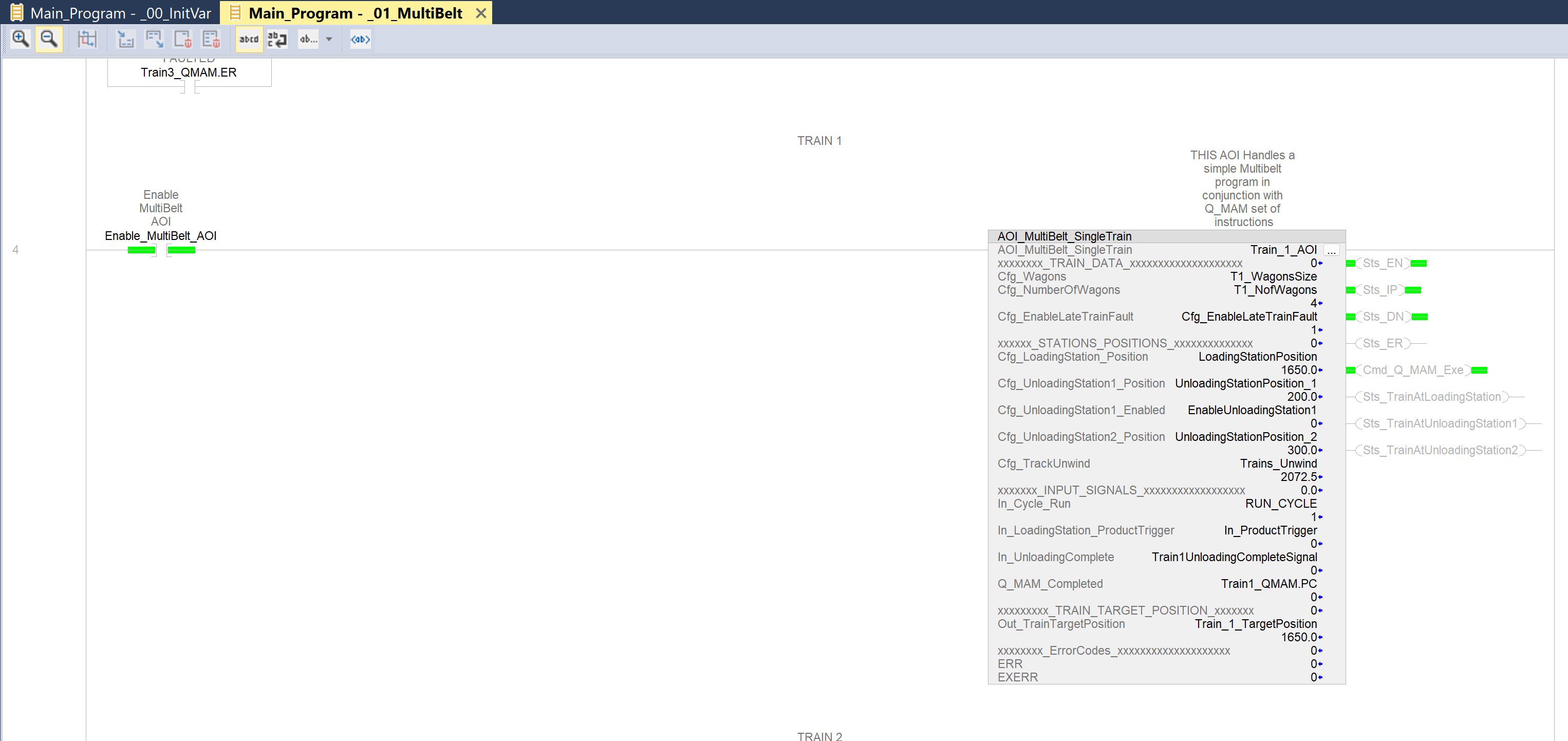
  • AOI_MultiBelt_SingleTrain


    Manages the sequence of a single train within the MultiBelt system. It determines the next target position based on the loading status, the number of loaded wagons and the unloading stations.


    When first enabled, it initializes Train_Cycle_State and Mem_Cycle_State, clears errors and resets the Train_Wagon_CTU counter.


    It checks that Cfg_NumberOfWagons is greater than zero, that the Cfg_Wagons array is large enough, that Cfg_TrackUnwind is valid, and that the loading and unloading positions are within the track range; if any check fails, it sets Sts_ER with codes 1005, 1006, 1007, 1008 or 1009.

    State

    Train action

    0

    Waits for cycle start

    10

    Commands a move to the loading station (Cfg_LoadingStation_Position)

    20

    Waits for confirmation that the Q_MAM move is complete

    30

    The train is at the loading station and processes product triggers

    50

    If unloading station 1 is enabled, commands a move to it

    60

    Waits for arrival and unloading at station 1

    70

    Commands a move to unloading station 2

    100

    Waits for arrival and unloading at station 2, then returns to state 10

  • State 999 corresponds to pause or error. When In_LoadingStation_ProductTrigger arrives, the AOI counts one wagon with Train_Wagon_CTU and, if not all wagons are loaded yet, calculates a new loading position by adding the size of the last loaded wagon and applying a modulo with Cfg_TrackUnwind, which generates successive targets around the circular track.


    The Cmd_Q_MAM_Exe output is set when the train must move, and Out_TrainTargetPosition passes the target position to the Q_MAM_P_V3 AOI.

    multibelt-conveyor-control_imagen 1.jpg

    multibelt-conveyor-control_imagen 1.jpg

  • AOI_MotionPlannerCountDown

    Calculates timing information for the motion planner. It reads TimeOffset, CoarseUpdatePeriod, StartTime and CycleStartTime from the motion group, reads the current CST time and converts it to planner time.


    From these values it obtains TimeLeft (time remaining until the next planner call), TimeElapsed (time elapsed since the last execution) and ActualizationTimeOffset (difference between the cycle start and the group start). If the motion group is not synchronized, it sets ER.


  • AOI_ReadInterpolatedActualPosition


    Reads interpolated positions from a CIP axis. It gets the current CST time, adds TimeOffset to it, writes that time as the axis InterpolationTime, and copies Axis.InterpolatedActualPosition and Axis.InterpolatedCommandPosition to its outputs.


    In this application it is used to estimate more accurately the command position of an axis within the planner interval and to feed the feedforward calculation.


  • Encoded Add-On Instructions

    The AOIs raM_Opr_EventCreate, _raM_Opr_DvcStateModel, _raM_Dvc_ModulePresent, raM_Dvc_CIPAxis and raM_Opr_SafeTrqOff_CD are sealed, and their internal logic cannot be inspected from the L5X. Their function is inferred from their names and visible interfaces: raM_Dvc_CIPAxis manages the CIP devices and axes associated with the drives, and raM_Opr_SafeTrqOff_CD implements the drives' Safe Torque Off.

Step 2
 

Environment preparation

Open the Q_MAM_P_v3_GL.acd file in a programming environment that supports Logix version 36 projects, and check that the target controller is a 1756-L84ES or compatible, major revision 36.

Before continuing, confirm that the following exist: the tasks SafetyTask, _01_MainTask and _03_MotionEventTask; the programs Main_Program, Main_Motion_Prg and SafetyProgram; the axes Ax_Train1, Ax_Train2, Ax_Train3, Ax_Converter and In_Belt; the Axes motion group; and the drive modules Drive_PowerSupply, Drive_1 and Drive_2 with their addresses.

Also confirm that the required AOIs are present in the project.

Step 3
 

Review before downloading

Check that the axes are correctly assigned to their drives and that the motion parameters are safe for the equipment or the simulator. Verify that the expected initial positions are compatible with the mechanics, that the mechanical conditions allow positive motion around the circular track, and that the system can stop the trains with the configured deceleration.
 

Initial command positions and stations

Element

Expected value

Ax_Train1 - initial command position

2000

Ax_Train2 - initial command position

1500

Ax_Train3 - initial command position

1000

LoadingStationPosition

1650.0

UnloadingStationPosition_1

200.0

UnloadingStationPosition_2

300.0

Train configuration and Q_MAM parameters

Parameter

Value

T1_NofWagons, T2_NofWagons, T3_NofWagons

4

Wagon sizes per train

60, 120, 60, 60

Calculated length per train

300

Q_MAM speed

2500

Q_MAM acceleration

15000

Q_MAM deceleration

15000

Acceleration jerk

33

Deceleration jerk

33

Target position tolerance

0.05

Calculated track unwind

approximately 2072.5

Step 4
 

Download and run mode

Go online with the controller or the simulation environment and download the project. If a full download is required, put the controller in Program mode; once the download is complete, switch to Run or Remote Run mode.

Verify that _01_MainTask runs periodically every 10 ms, that _03_MotionEventTask is associated with the Motion Group Execution event, and that SafetyTask runs every 20 ms. Finally, confirm that the Axes group is synchronized through Axes.GroupSynced: this condition enables the entire subsequent sequence.
 

Step 5
 

Automatic initialization

When scanning starts, Main_Rtn waits for Axes.GroupSynced to be active and starts the ProgramScanDelay timer. While ProgramScanDelay.DN is not set, Main_Rtn calls _00_InitVar and temporarily halts the rest of the application scan with TND, so that configuration and position variables are initialized before normal sequences are allowed.

_00_InitVar sets InitializeVariables and internally redefines the train command positions when they do not match the expected initial positions. It then uses GSV instructions to read the CoarseUpdatePeriod of the Axes group and convert it to seconds, and reads TravelMode, ConversionConstant and PositionUnwind from each axis to calculate Train1_Unwind, Train2_Unwind and Train3_Unwind.

If the three unwind values are equal and all three axes have TravelMode equal to 2, the common value is copied to Trains_Unwind and TrainsConfCorrect is set. The routine then loads the station positions, leaves EnableUnloadingStation1 off, configures the four wagons per train with their sizes, calculates each train's length using LBL and JMP loops, and writes the common Q_MAM parameters to Train_1_QMAM_Data, which are then copied to Train_2_QMAM_Data and Train_3_QMAM_Data.

Finally, it assigns each train's minimum distance based on the length of the preceding train and turns off RUN_CYCLE and CycleSimulationEnabled, leaving the system in a safe waiting state.

Step 6
 

Safety check before starting

Confirm that the drives' Safe Torque Off inputs are healthy, that Train_SafeTorqueOff.Inp_SafetyInterlockOK is active, that there are no active errors in Train_SafeTorqueOff.Sts_ER, and that Train_SafeTorqueOff.Sts_TorqueDisabled correctly reflects the STO state of the trains. If a safety reset is required, momentarily set SafetyResetRequest.

SafetyProgram.MainRoutine copies that request to Train_SafeTorqueOff.Cmd_Reset and calls Trains_SafeTorqueOff, which distributes Cmd_Reset, Cfg_AutoReset, Cfg_StopCategory and Cfg_StopTime to the three internal instances _Trains_SafeTorqueOff_M1, _Trains_SafeTorqueOff_M2 and _Trains_SafeTorqueOff_M3. M1 and M2 are connected to safety signals 1 and 2 of Drive_1, and M3 to safety signal 1 of Drive_2.

Train_SafeTorqueOff.Sts_TorqueDisabled is set when all three instances report torque disabled, and Sts_MotionStop when all three report motion stopped. If any instance reports an error, its Sts_ERR and Sts_EXERR codes are copied to the global object and Train_SafeTorqueOff.Sts_ER is set. Do not request a start while safety conditions are inhibiting motion.
 

Step 7
 

Application fault reset

Momentarily set FaultReset_Cmd. The FaultResetCycle sequence steps through numbered states and ends at 999 when the reset completes successfully.

FaultResetCycle state

What should happen

10

Confirm that the safety interlock is OK and that AxesTorqueDisabled reflects the expected state for reset; SafetyResetCmd is generated when applicable. The cycle advances to 20 once torque is no longer disabled

20

If AxesFaultedState is active, AxesResetFault_Cmd is set and _99_AxManager generates ClearFaults for the faulted axes. The cycle advances to 30 when no axes are faulted

30

ApplicationMotionError is cleared if it was active and, if AbortCycle existed, Trains_ResetCycle is generated

999

Reset cycle complete

Step 8
 

Axis start-up

Verify that AxesAvailableState is active, AxesFaultedState is inactive and AxesTorqueDisabled is inactive before enabling motion. Then momentarily set StartUp_Cmd and confirm that StartUpCycle moves to state 10.

AxesOn_Cmd is set when the axes are available, not faulted, not torque-disabled and not yet activated. In _99_AxManager you should see AxT1_Ctrl_Cmd.Activate, AxT2_Ctrl_Cmd.Activate and AxT3_Ctrl_Cmd.Activate being generated, provided the corresponding axis does not have Safe Torque Disabled and the device is available. When AxT1_Ctrl_Sts.Activated, AxT2_Ctrl_Sts.Activated and AxT3_Ctrl_Sts.Activated are all active, AxesON becomes true and StartUpCycle ends at 999.
 

Step 9
 

MultiBelt cycle start

With AxesON, TrainsConfCorrect and RunCycleEnabled active, momentarily set RunCycle_Cmd. RunCycleState moves to state 10 and RUN_CYCLE is latched. If running is not permitted, the sequence is invalidated with a negative state.

_01_MultiBelt sets Enable_MultiBelt_AOI when Axes.GroupSynced and InitializeVariables are true and Trains_ResetCycle is not active. This runs the three instances Train_1_AOI, Train_2_AOI and Train_3_AOI of AOI_MultiBelt_SingleTrain. Each instance receives its wagon-size array, the number of wagons, the loading and unloading positions, the track unwind, the RUN_CYCLE status, the In_ProductTrigger product trigger, the unloading-complete signal and the move-complete status of its Q_MAM, and returns Out_TrainTargetPosition.

The routine declares MultiBelt_Ready when the cycle is active and at least one train is at the loading station, and consolidates the AOI errors: if any train reports Sts_ER, MultiBelt_Cycle_Error is set and RUN_CYCLE is turned off. Each AOI sets Cmd_Q_MAM_Exe when it needs to move its train.
 

Step 10
 

Q_MAM move execution

Move_Commands blocks its execution while ProgramScanDelay.DN is not set, which prevents motion commands from being sent before initialization is complete. It then calls the Q_MAM_P_V3 AOI for each train when the corresponding train AOI requests it through Cmd_Q_MAM_Exe. The chaining of preceding axes and linked parameters is circular.

Train

Q_MAM instance

Target

Axis

Preceding axis

Linked parameters (input / output)

1

Train1_QMAM

Train_1_TargetPosition

Ax_Train1

Ax_Train3

Train3_LinkedParametersOutput / Train1_LinkedParametersOutput

2

Train2_QMAM

Train_2_TargetPosition

Ax_Train2

Ax_Train1

Train1_LinkedParametersOutput / Train2_LinkedParametersOutput

3

Train3_QMAM

Train_3_TargetPosition

Ax_Train3

Ax_Train2

Train2_LinkedParametersOutput / Train3_LinkedParametersOutput

Monitor Train1_QMAM.PC, Train2_QMAM.PC and Train3_QMAM.PC: each Cmd_Q_MAM_Exe must be cleared when its corresponding Q_MAM reports PC, which turns each request into a controlled execution and prevents the same command from being re-executed continuously. Also watch Train1_QMAM.ER, Train2_QMAM.ER and Train3_QMAM.ER to detect motion errors, and Sts_Queued, Sts_QueueLeader, inf_TrainsActualDistance and Sts_Mover_WayFree on each Q_MAM to validate the spacing between trains.

Step 11
 

Product loading

For a manual test, generate a pulse on In_ProductTrigger. To use the simulation, set CycleSimulationEnabled while RUN_CYCLE is active: ProductGenerationTimeDelay times the product generation, InfeedBeltProductInput_FallingEdge generates a pulse, and that pulse sets In_ProductTrigger for one scan.

Confirm that the AOI of the train at the loading station increments its Train_Wagon_CTU counter and that the loading target advances according to the size of the loaded wagon. Repeat until the four configured wagons are complete: when the counter reaches them, the train is reset and moves on to the unloading sequence.

Step 12
 

Product unloading

Observe Sts_TrainAtUnloadingStation1 and Sts_TrainAtUnloadingStation2 in Train_1_AOI, Train_2_AOI and Train_3_AOI. When a train reaches an unloading station, its corresponding timer (UnloadTrain1, UnloadTrain2 or UnloadTrain3) starts and, when it finishes, the unloading-complete signal Train1UnloadingCompleteSignal, Train2UnloadingCompleteSignal or Train3UnloadingCompleteSignal is generated. That signal generates Trigger_Products_Unloaded and is then cleared.

Confirm that the train AOI receives In_UnloadingComplete, advances to the next state and returns to the loading sequence. Because EnableUnloadingStation1 is initialized off, the logic may skip the first unloading station and use the second one as the main unloading point.

multibelt-conveyor-control_imagen 2.jpg

multibelt-conveyor-control_imagen 2.jpg

Step 13
 

Infeed belt

When RUN_CYCLE becomes active, a start pulse is generated for _03_AxBelt and AxBelt_CycleState moves to state 10. In that state, In_Belt is jogged with the configured speed, acceleration, deceleration and jerk parameters, and once In_Belt.JogStatus confirms, the state advances to 20. When RUN_CYCLE turns off, _03_AxBelt issues another jog command at zero speed to stop the belt, and AxBelt_CycleState returns to 0 when In_Belt.JogStatus turns off.

Step 14
 

Recommended monitoring during execution

Group

Tags to monitor

General status

RUN_CYCLE, RunCycleEnabled, RunCycleState, ApplicationMotionError, AbortCycle, MultiBelt_Cycle_Error

Axes

AxesON, AxesAvailableState, AxesFaultedState, AxesTorqueDisabled

Trains

Sts_IP and Sts_ER of Train_1_AOI, Train_2_AOI and Train_3_AOI; Train_1_TargetPosition, Train_2_TargetPosition and Train_3_TargetPosition

Q_MAM

IP, PC, ER, ERR and EXERR of Train1_QMAM, Train2_QMAM and Train3_QMAM

Visualization

To_E3D_T1_CmdPos, To_E3D_T2_CmdPos, To_E3D_T3_CmdPos


To observe the dynamic behavior, use the trends already included in the project: Q_MAM_V3, Train1To2Distance, Train1_LinkedParametersOutput_PP, Train1_QMAM_Sts_QueueLeader, Trains, Trains1n2 and Train_1.

Step 15
 

Normal stop

Momentarily set StopCycle_Cmd. RUN_CYCLE turns off and RunCycleState returns to 0. _01_MultiBelt clears Cmd_Q_MAM_Exe in the three train AOIs and issues stop commands for Ax_Train1, Ax_Train2 and Ax_Train3 with the configured deceleration and jerk, while _03_AxBelt stops In_Belt. Confirm that the axes have no active motion before disabling torque.
 

Step 16
 

Fault or abort stop

If ApplicationMotionError occurs, StopCycle_Cmd and AbortCycle are set, RUN_CYCLE turns off, the Q_MAM commands are cleared and motion stops are executed for all three trains. Identify the source of the fault in Train1_QMAM.ER, Train2_QMAM.ER and Train3_QMAM.ER, in Sts_ER of the three train AOIs, in AxesFaultedState and in Train_SafeTorqueOff.Sts_ER.

Correct the root cause before resetting. Then run the fault reset procedure using FaultReset_Cmd, and repeat the axis start-up and cycle start only when there are no active faults.

Step 17
 

System shutdown

First perform the normal stop with StopCycle_Cmd and confirm that there is no active motion. If the system must be left with servos disabled, deactivate the axes with AxesOff_Cmd: _99_AxManager generates the deactivation commands for the activated axes and AxesON turns off. Then apply the safety or STO conditions according to the machine procedure, and put the controller in Program mode only if the plant procedure requires it.

Expected conditions for a correct run

  • Axes.GroupSynced active and TrainsConfCorrect active.
  • AxesON active after start-up and RunCycleEnabled active.
  • RUN_CYCLE active during operation.
  • The three train AOIs without Sts_ER and the three Q_MAM instances without ER.
  • The Cmd_Q_MAM_Exe commands are set on each motion request and cleared when PC is reached.
  • The target positions change as wagons are loaded and the trains advance toward the unloading stations.
  • The distance between trains stays above the configured minimum distance.
  • The normal stop turns off the cycle and stops the trains and the belt.
 
multibelt-conveyor-control_imagen 1.jpg

multibelt-conveyor-control_imagen 1.jpg

multibelt-conveyor-control_imagen 2.jpg

multibelt-conveyor-control_imagen 2.jpg


Multibelt Conveyor Control

Version 1.0 - September 2026


AHIC White Logo

Receive new applications and Innovation Center updates directly in your inbox.

Subscribe!
 
  1. Chevron LeftChevron Left Rockwell Automation Home
  2. Chevron LeftChevron Left Sup...
  3. Chevron LeftChevron Left Pro...
  4. Chevron LeftChevron Left Downloads
  5. Chevron LeftChevron Left Innovation Center
  6. Chevron LeftChevron Left Multibelt Conveyor Control
Please update your cookie preferences to continue.
This feature requires cookies to enhance your experience. Please update your preferences to allow for these cookies:
  • Social Media Cookies
  • Functional Cookies
  • Performance Cookies
  • Marketing Cookies
  • All Cookies
You can update your preferences at any time. For more information please see our {0} Privacy Policy
CloseClose