Downloads

Micro800 and Kinetix 5100 Practical Setup

What is this for?
The main goal of this application is to provide engineering teams—whether from end users, integrators, OEMs, etc.—with a ready-to-use startup program for any motion control project involving Kinetix 5100, Micro 800, and PanelView 800.
The executable files for running the motion control application were developed using the software environments of Connected Components Workbench (for programming the Micro 800 and PanelView 800) and KNX5100C (for configuring the Kinetix 5100 drive). These files include the necessary program and configuration to control the Micro800, the parameters for the K5100, and the HMI program.
Is this useful for me?
This application was designed with a basic and easily accessible bill of materials, allowing users to execute it with minimal complexity. Additionally, it is fully functional for any industry that requires a simple motion control solution.
All of this provides numerous advantages, such as establishing a common foundation for future projects after understanding and working with this type of application. It also helps reduce development and commissioning time for new applications, benefiting plant control and automation teams, integrators, and OEMs. Moreover, it serves as a practical tool for technical training and concept testing, while enhancing understanding of motion control and related topics.
Please note: You will need to agree to the Terms & Conditions for each download.
Need Help?
If you need help with an application or have feedback from the Innovation Center, please contact us.
How can I make it work?Requirements: products, tools, prior knowledge.
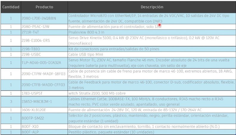
Hardware
Software
- Connected Components Workbench (V23 or higher)
- KNX5100C (V 4.0 or higher)
Knowledge
- Basic knowledge of programming and configuration in Connected Components Workbench (CCW) software, as well as experience with programming and using Micro 800, PanelView 800, and Kinetix 5100 using the configuration software KNC5100C.
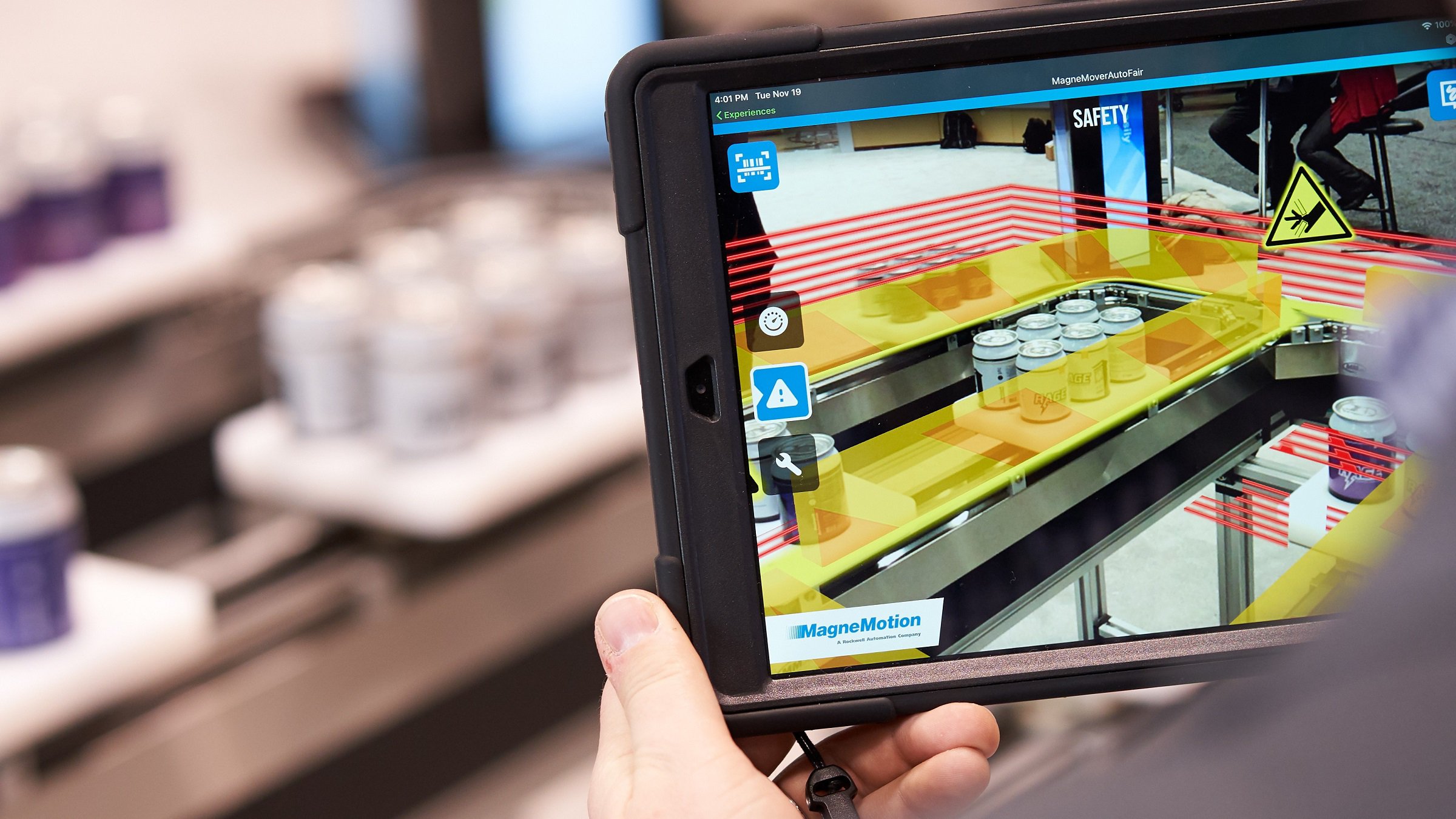
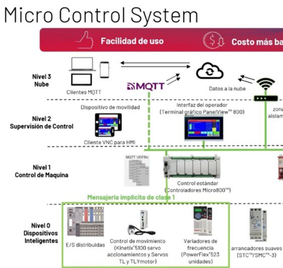
- Understanding the Micro Control System Environment.
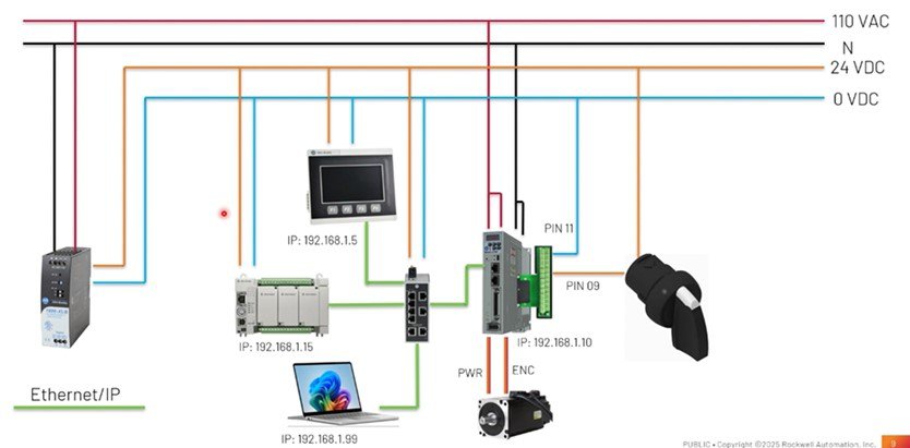
- Architecture Scheme & connections for application use
Manuals / Technical Notes
Inside the folder available for download along with the application files, you will find three manuals that complement the usage and understanding of the various components and devices used in this application. These are:
- CCW: Using project from Sample Code Library
- Connected Components Workbench v21: Implicit messaging UDFBs for Kinetix 5100 and PowerFlex 520-series drives
- Micro830, Micro850, and Micro870 Programmable Controllers

Implementation Guide
- Step 1
- Step 2
- Step 3
- Step 4
- Step 5
- Step 6
Step 1
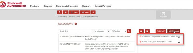
Step 1: Download Design and Configuration Software – CCW & KNC5100C
From the Rockwell Automation downloads page, you can search and download each of the mentioned software tools by name.
Once downloaded, install them to have them available for the necessary configuration tasks.
micro800-and-kinetix-5100-practical-setup_Picture4.jpg
Step 2
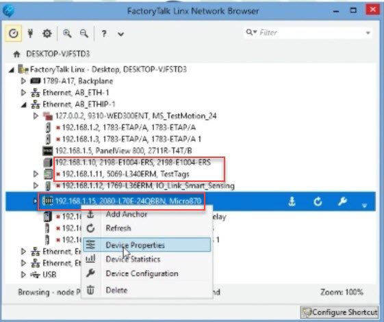
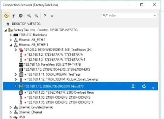
Step 2: FT Linx Configuration – Firmware Version Verification
You must verify Ethernet connectivity with the respective devices using FT Linx, ensuring that the firmware versions are up to date.
micro800-and-kinetix-5100-practical-setup_Picture5.jpg
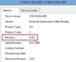
After confirming proper connectivity, it is important to verify that all devices have the latest firmware versions installed.
micro800-and-kinetix-5100-practical-setup_Picture6.jpg
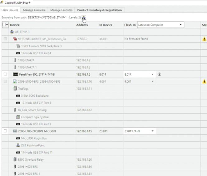
If the firmware is not up to date, it can be updated using the ControlFLASH Plus application, which is automatically installed alongside Connected Components Workbench.
micro800-and-kinetix-5100-practical-setup_Picture7.jpg
Step 3
Step 3: Drive Configuration in KNX5100C
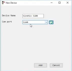
Open the attached downloadable file K5100_Project_3_OK.prj in the KNX5100C software.
Confirm the assigned USB port for connection.
micro800-and-kinetix-5100-practical-setup_Picture8.jpg
We download the project to the drive.
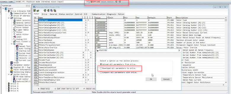
micro800-and-kinetix-5100-practical-setup_Picture9.jpg
micro800-and-kinetix-5100-practical-setup_Picture10.jpg
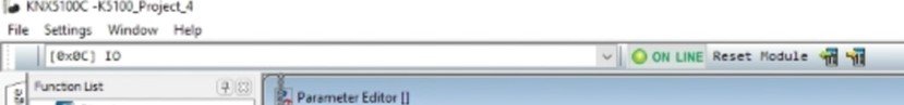
Once the previous procedure is completed, the system should be running online and functioning correctly.
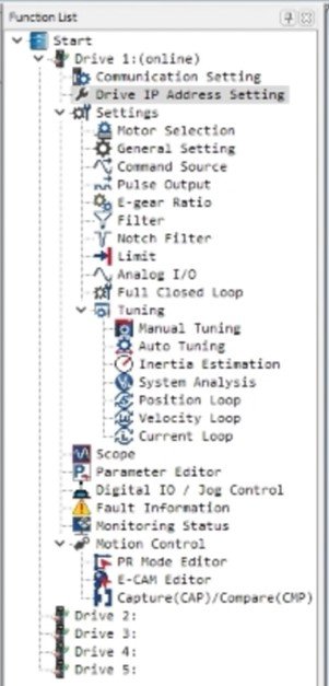
Next, proceed to review and confirm the various main program settings required for proper operation, such as assigning the IP address and configuring the communication settings.
micro800-and-kinetix-5100-practical-setup_Picture11.jpg
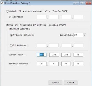
micro800-and-kinetix-5100-practical-setup_Picture12.jpg
Other Important Settings to Configure:
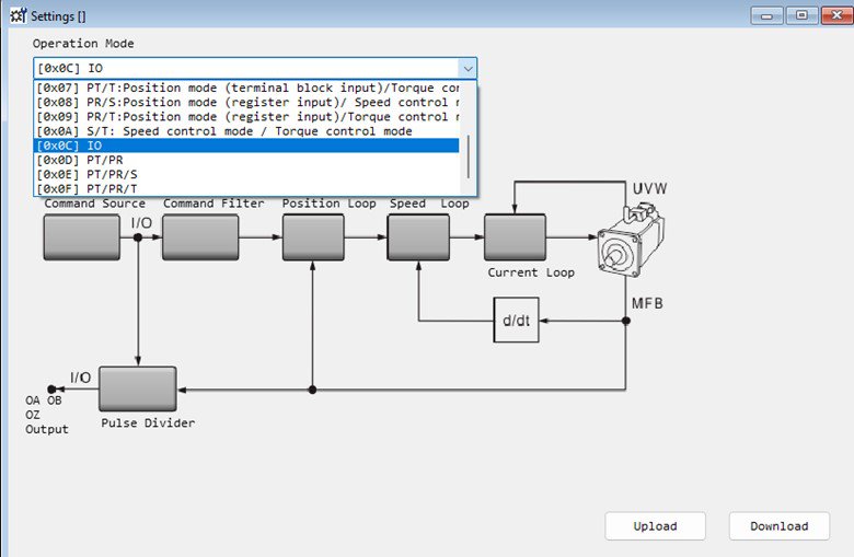
micro800-and-kinetix-5100-practical-setup_Picture13.jpg
Operation Mode I/O → This setting defines the operation mode, allowing another device to control the drive—in this case, the Micro800.
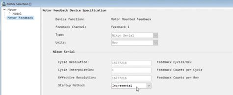
Motor Selection → By choosing the catalog number option, you must enter the catalog number of the TLP motor proposed in the bill of materials section. Then, confirm the incremental operation method.
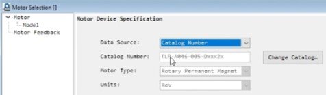
micro800-and-kinetix-5100-practical-setup_Picture14.jpg
micro800-and-kinetix-5100-practical-setup_Picture15.jpg
micro800-and-kinetix-5100-practical-setup_Picture16.jpg
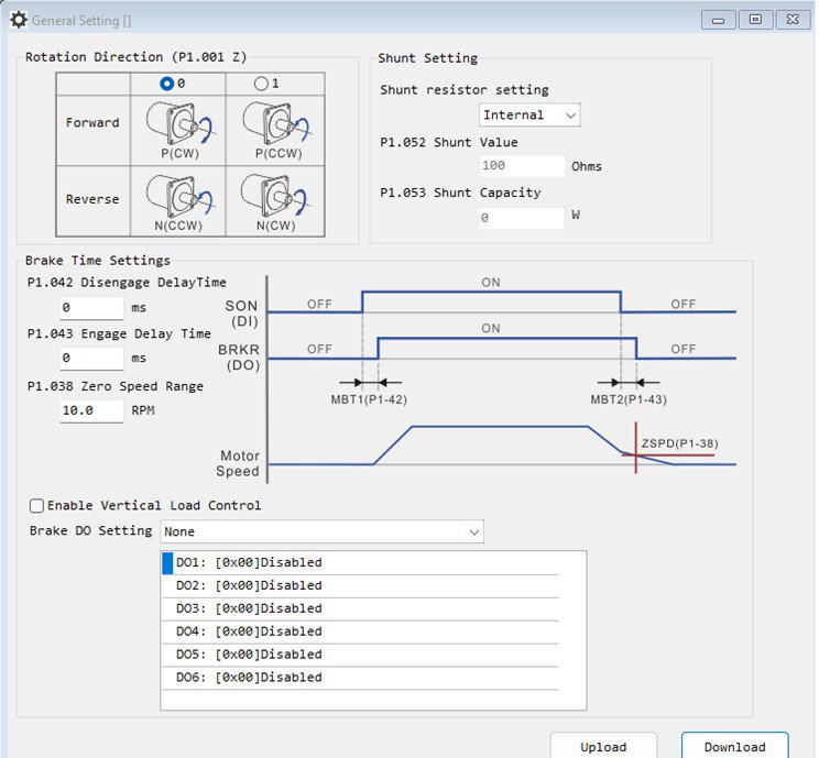
General Setting → We can configure rotation direction (1), if we using a braking resistor – we can define its parameters (2). Its available the option to enable the braking option and set the braking time (3), finally, we can configure the zero speed detection – and its notification (4)
micro800-and-kinetix-5100-practical-setup_Picture17.jpg
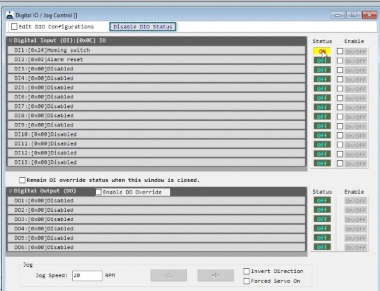
Digital I/O → Inputs are assigned according to the application requirements. For this case, confirm that the first input is set as “Homing Switch”, and perform the necessary status and functionality tests—mainly to ensure proper connection, as shown in the corresponding image.
Step 4
Step 4 – CCW Configuration
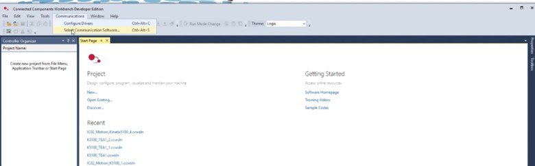
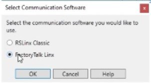
Initially, it is necessary to confirm in the communications settings that the communication software being used is FT Linx.
micro800-and-kinetix-5100-practical-setup_Picture18.jpg
micro800-and-kinetix-5100-practical-setup_Picture19.jpg
Then, proceed to import the project included in the application’s attached files:
K5100_Class1_UDFBs_with_PV800_Sample_Screens.ccwarc
micro800-and-kinetix-5100-practical-setup_Picture20.jpg
Note: For future use of the project, it is important to save it locally on your PC using: File → Save Project As
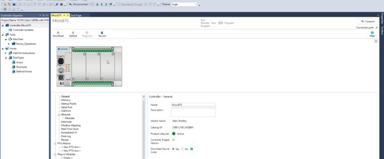
The first adjustment must be made in the Micro 870 controller. Right-click on the controller and select Controller Change, then choose the catalog number of the device you are working with in practice (refer to the bill of materials at the beginning of the documentation).
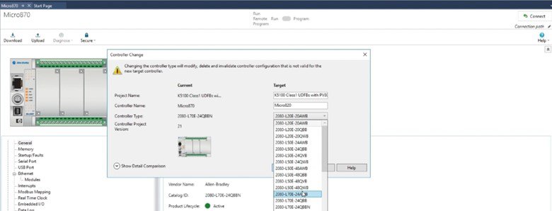
micro800-and-kinetix-5100-practical-setup_Picture21.jpg
After completing this step, go to the Ethernet settings in the controller options and confirm that the IP address is correctly configured according to the criteria defined earlier.
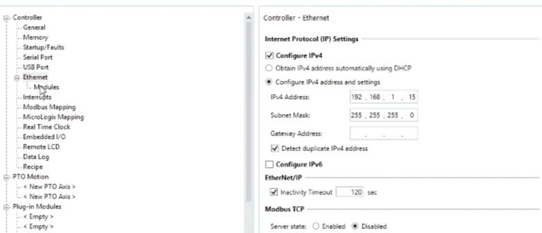
micro800-and-kinetix-5100-practical-setup_Picture22.jpg
Finally, in the Modules section, ensure that the settings match those shown in the reference image. This step confirms that the device connected to the Micro800 via Ethernet is the correct Kinetix 5100 drive, and verifies its IP address, connection status, and module compatibility.
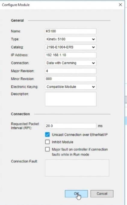
micro800-and-kinetix-5100-practical-setup_Picture23.jpg
Step 5
Step 5 – Panel View 800 Configuration
micro800-and-kinetix-5100-practical-setup_Picture24.jpg
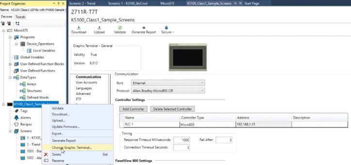
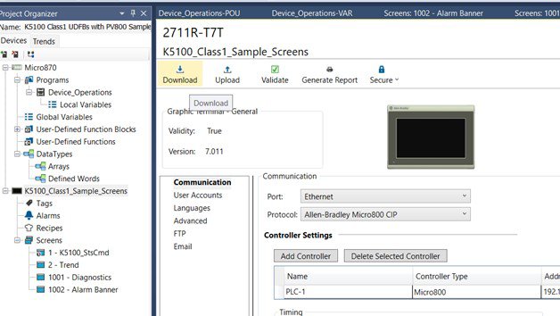
Just as we began with initial adjustments for the Micro800 configuration, in this case, we will perform the first setup for the PanelView 800, changing the screen type in the project to match the one selected in the previously proposed bill of materials.
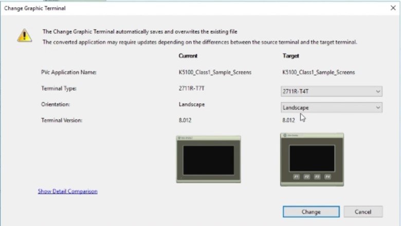
micro800-and-kinetix-5100-practical-setup_Picture25.jpg
micro800-and-kinetix-5100-practical-setup_Picture26.jpg
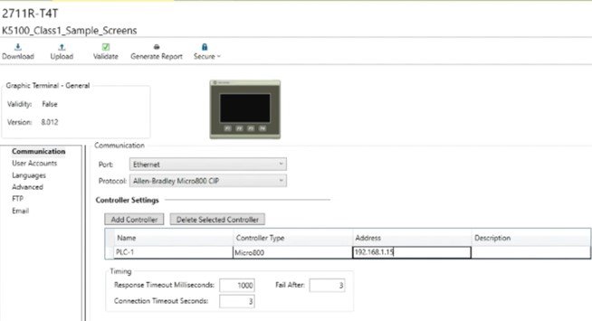
It is important to confirm (and adjust if necessary) the IP address defined earlier, ensure the use of the Ethernet port, and verify that the CIP industrial communication protocol is selected. The remaining settings can be left as default.
This application is designed to work with two screens, The main screen is composed as follows in the next picture:
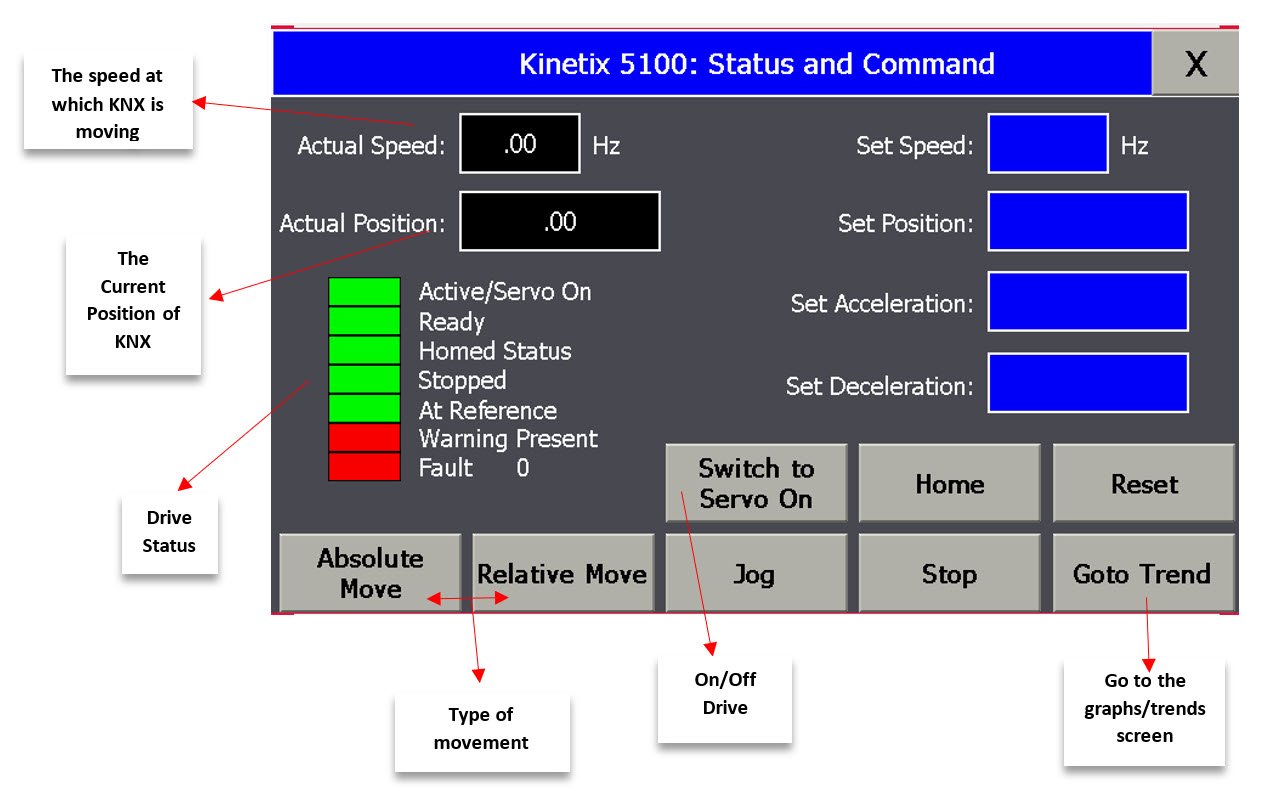
micro800-and-kinetix-5100-practical-setup_Picture27.jpg
The second screen focuses on graphing trends and servo motor behavior over time. Additionally, the buttons used on this screen are essentially the same as those on the main screen, with their respective functions.
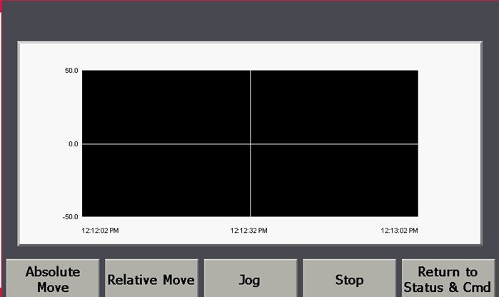
micro800-and-kinetix-5100-practical-setup_Picture28.jpg
Step 6
Step 6 – Commissioning & Demostration
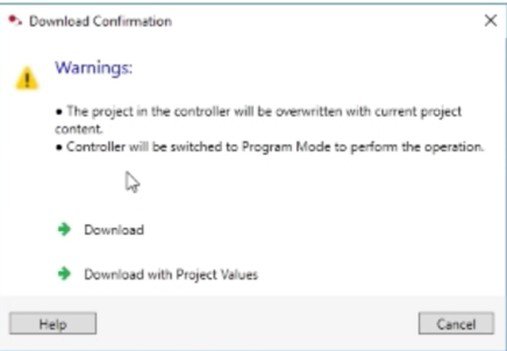
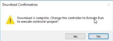
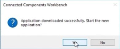
After completing the previous configurations, everything is ready to download the program to the Micro800 controller and verify the proper operation of the application.
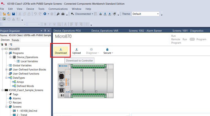
micro800-and-kinetix-5100-practical-setup_Picture29.jpg
micro800-and-kinetix-5100-practical-setup_Picture30.jpg
micro800-and-kinetix-5100-practical-setup_Picture31.jpg
micro800-and-kinetix-5100-practical-setup_Picture32.jpg
You must also download the program to the PanelView 800. This process follows similar steps.
micro800-and-kinetix-5100-practical-setup_Picture33.jpg
micro800-and-kinetix-5100-practical-setup_Picture34.jpg
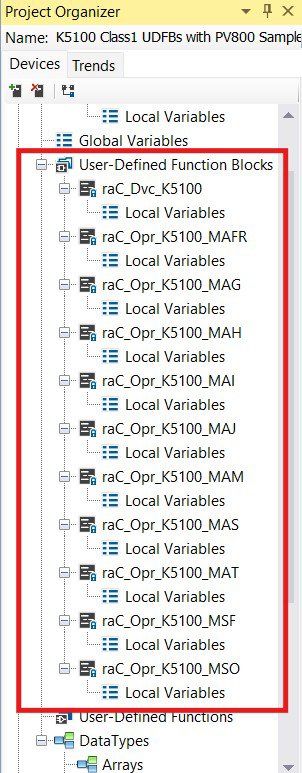
The following image highlights all the libraries required to program drive control in the Micro800 controller. It is recommended that, if you plan to work on similar new projects, you read and follow the steps outlined in the technical notes/manuals shared in the Links of Interest section:
- Connected Components Workbench v21: Implicit messaging UDFBs for Kinetix 5100 and PowerFlex 520-series drives
- CCW: Using project from Sample Code Library
micro800-and-kinetix-5100-practical-setup_Picture35.jpg
All these libraries are reused in the design of the main program within the project
micro800-and-kinetix-5100-practical-setup_Picture36.jpg
micro800-and-kinetix-5100-practical-setup_Picture37.jpg
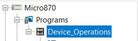
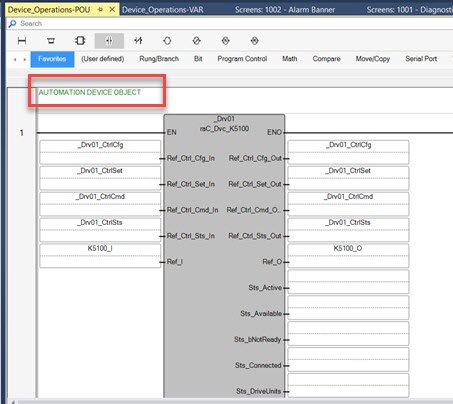
The DEVICE OBJECT is the main block of the program. As you progress through the functional block code, you will find the programming for all the buttons shown on the screens and other components of the application.
micro800-and-kinetix-5100-practical-setup_Picture38.jpg

micro800-and-kinetix-5100-practical-setup_Picture39.jpg
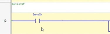
For example, the previous images show the programming of the drive ON/OFF button.
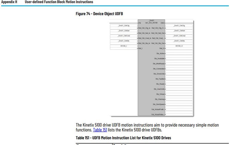
Another important manual we recommend reviewing to understand the DEVICE OBJECT configuration (also linked in the Links of Interest) is:
- Micro830, Micro850, and Micro870 Programmable Controllers / Appendix H – User-defined Function Block Motion Instructions
This manual contains the necessary information to configure the block for the Kinetix 5100, including its instructions and descriptions.
micro800-and-kinetix-5100-practical-setup_Picture40.jpg
It is essential to create a DEVICE OBJECT for each drive assigned to the Micro800 controller, especially if the project or application requires working with multiple drives.
We recommend reviewing the full appendix in detail to fully understand how these instruction blocks can be programmed according to the needs and objectives of your applications or projects.
micro800-and-kinetix-5100-practical-setup_Picture41.jpg
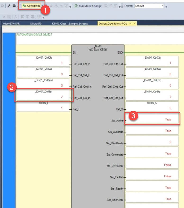
With the application running and initial tests confirming proper operation, you can begin by:
- Verifying the connection with the Micro800
- In the DEVICE OBJECT block, checking the Control Status – 7, which indicates readiness to receive instructions
- Confirming that Active = True, meaning the servo motor is “ON” and ready to start
One way to verify the application’s performance is by using the Scope feature in KNX5100C, the drive configuration software.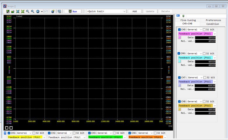
micro800-and-kinetix-5100-practical-setup_Picture42.jpg
One way to verify the application’s performance is by using the Scope feature in KNX5100C, the drive configuration software.
micro800-and-kinetix-5100-practical-setup_Picture43.jpg
micro800-and-kinetix-5100-practical-setup_Picture44.jpg
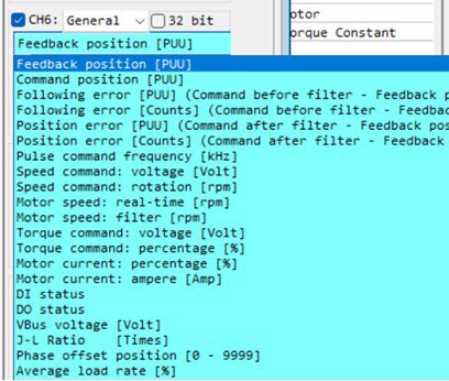
You can also change the channels to monitor other variables relevant to your objectives.
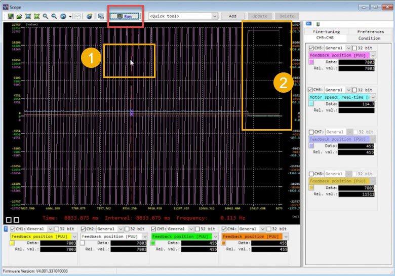
By clicking the Run button to start and begin graphing the system’s response, you gain access to multiple options within the Scope function in KNX5100C. This is the key information to understand for your motion control startup application.
A clear example is the data available in the graph: as shown in the previous image, you can place the cursor at any point in time(1) and, using the channel info boxes, identify the values of the selected variables—position and speed—at that specific moment.
You can also observe changes over time. For instance, when speed drops to zero(2), the servo motor’s position remains fixed from that moment onward.
Micro800 and Kinetix 5100 Practical Setup
Version 1.2 - May 2026