AVC wiring and programming example
This topic demonstrates how to program the instruction in the safety control portion of an application.
TIP:
The standard control portion of the application is not shown in the following diagram.
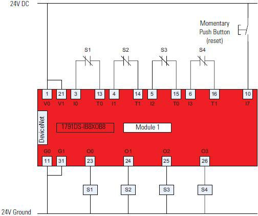
Wiring Diagram
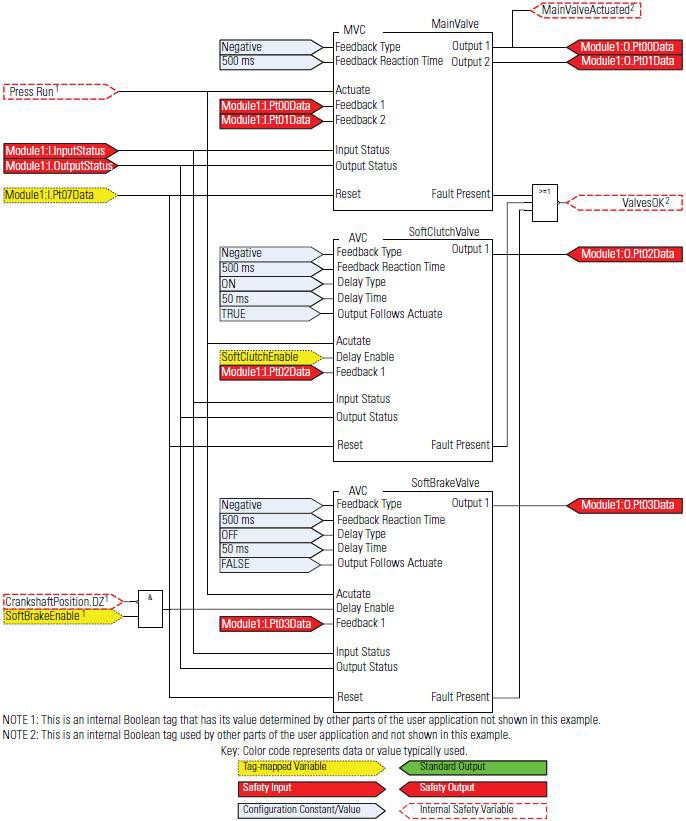
Programming Diagram
This programming diagram shows the Auxiliary Valve Control (AVC) instruction used with a Main Valve Control (MVC) instruction.
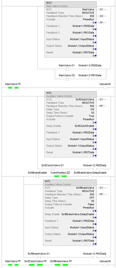
Ladder Diagram
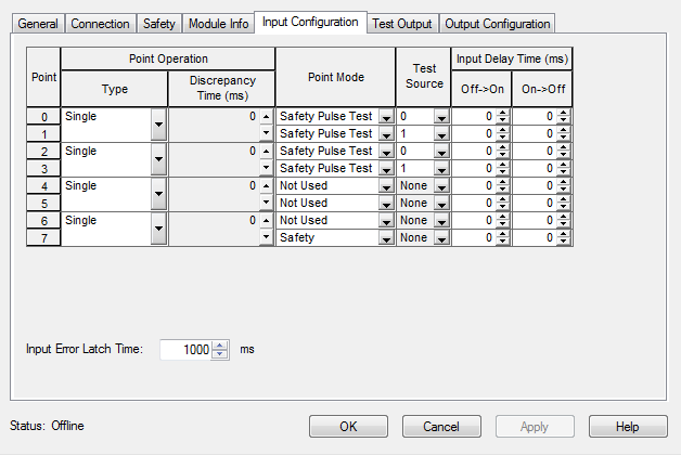
The Logix Designer application is used to configure the input and test output operands of the Guard I/O, as illustrated.
Module Definition
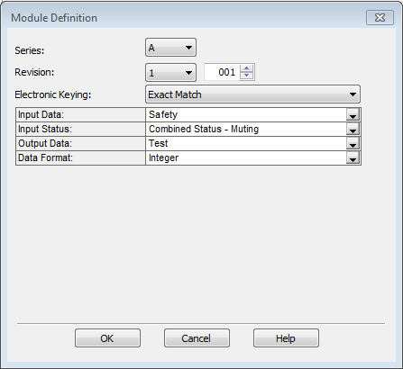
Rockwell Automation
suggests using Exact Match, as shown. However, setting Electronic Keying to Compatible Match is allowed.Module Input Configuration
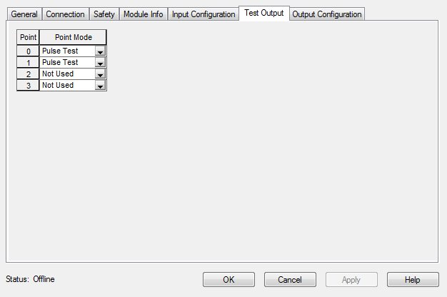
Module Test Output Configuration
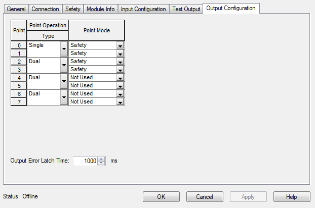
Module Output Configuration
Provide Feedback